
Substrate conveyer robot

Inactive Publication Date: 2007-03-20
HIRATA & CO LTD
View PDF6 Cites 10 Cited by
  • Summary
  • Abstract
  • Description
  • Claims
  • Application Information

AI Technical Summary

Benefits of technology

[0012]The present invention has been made with a view toward solving the above-described problems of the conventional substrate conveyer robots, and an object of the invention is to provide a substrate conveyer robot that can insert and remove a substrate to and from a container disposed in an arbitrary position and orientation, within an accessible range of the robot hand, with a minimum number of control axes, and at a low production cost.
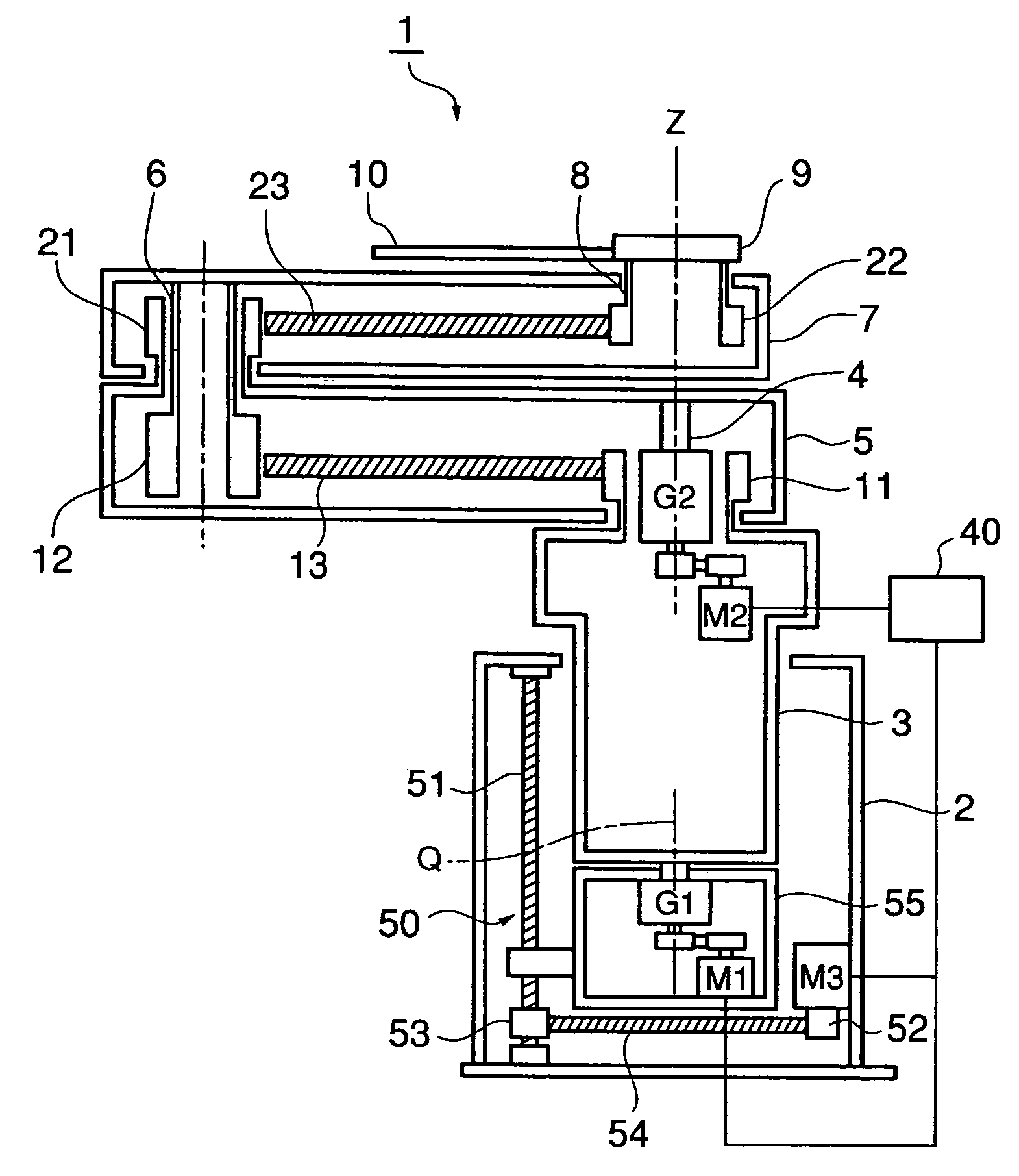
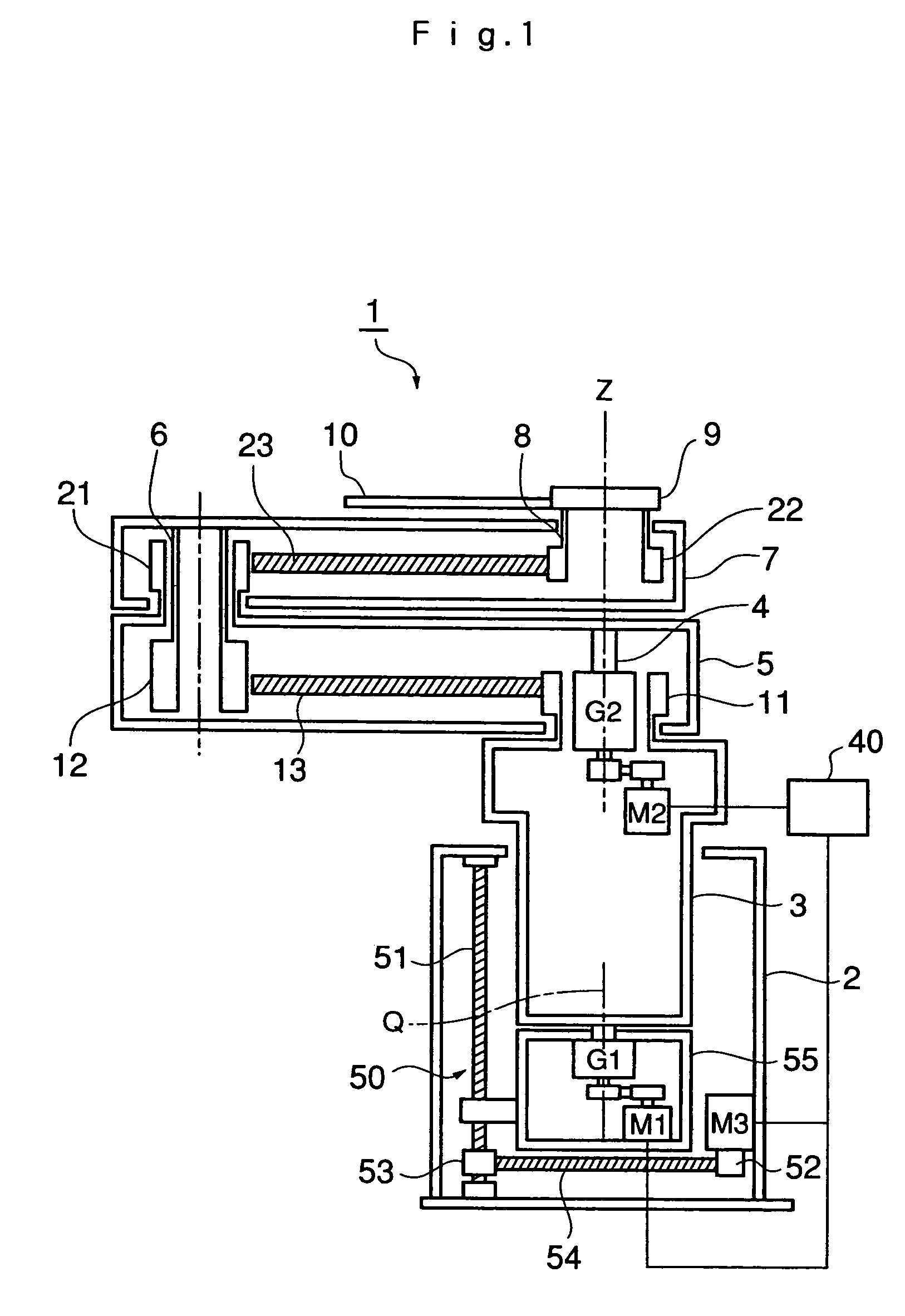
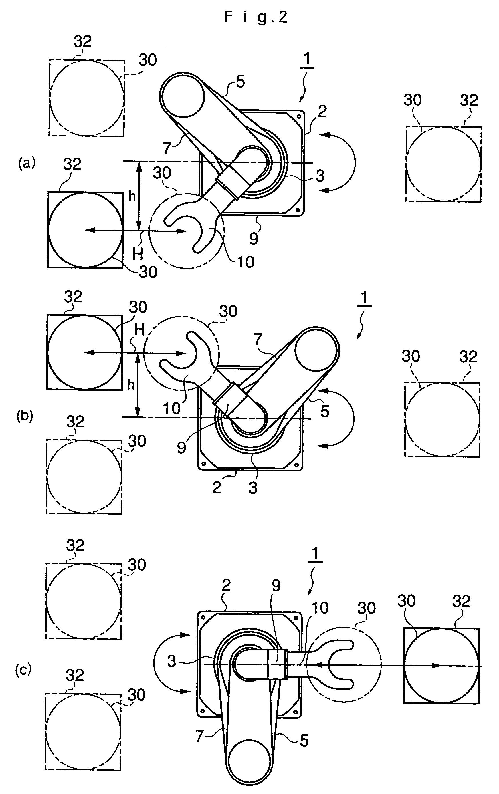
[0014]The substrate conveyer robot with the above construction is a so-called single arm sequence type substrate conveyer robot having a single sequence arm expansion / contraction mechanism that contains the first through third arms 5, 7, and 9. The control device controls the angle of rotation θ of the rotatable base 3 provided in the body of the robot and the angle of rotation φ of the first arm 5, in such a manner that the center point of the substrate held by the hand 10, spaced from the pivotal center Q, moves linearly relative to the body of the robot on the straight line H in an arbitrary direction within the accessible range of the hand 10, and the substrate is inserted into and removed from the container, while the substrate is being rotated. Therefore, in contrast to the conventional single arm sequence type substrate conveyer robot, the invention provides a substrate conveyer robot that can insert and remove the substrate to and from the container disposed in an arbitrary position and direction within the accessible range of the hand 10 of the robot, without increasing the number of control axes, at a low production cost.
[0015]Further, in the foregoing construction, the control device preferably controls the rotation angles θ and φ each so as to satisfy:{m+2 L sin (φ)} sin (θ)=h (constant),where it is assumed that the center point of the substrate is spaced from the pivotal center Q by a constant distance h, and moves linearly relative to the body of the robot on the straight line H in an arbitrary direction within the accessible range of the hand 10, and that the distance between the first spindle 4 and the second spindle 6 and the distance between the second spindle 6 and the third spindle 8 are represented by L, and that the distance between the third spindle 8 and the center of the substrate is represented by m. As the result, the combination control of these angles of rotation θ and φ becomes very simple, with the center point of the substrate held by the hand 10, spaced from the pivotal center Q, moved linearly relative to the body of the robot on the straight line H in an arbitrary direction within the accessible range of the hand 10, and the substrate is inserted into and removed from the container, while being rotated.
[0017]The substrate conveyer robot with the above construction is a so-called double arm sequence type substrate conveyer robot having two sequences, i.e., a pair of arm expansion / contraction mechanisms, which contain first through third arms 5, 5′, 7, 7′, and 9, 9′ respectively, in a bilateral symmetry. The control device controls the angle of rotation θ of the rotatable base 3 provided in the body of the robot and the angles of rotation φ, φ′ of the first arms 5, 5′, so that the center points of the substrates held by the hands 10, 10′, offset from the pivotal center Q, move linearly relative to the body of the robot along the straight lines H, H′ in arbitrary directions, within the accessible ranges of the hands 10, 10′, and the substrates are inserted into and removed from the container(s), while being rotated. Therefore, in contrast to the conventional double arm sequence type substrate conveyer robot, the invention provides a substrate conveyer robot that can insert and remove the substrates to and from the containers disposed in arbitrary positions and directions within the accessible ranges of the hands 10, 10′ of the robot, without increasing the number of the control axes, at a low production cost.
[0018]Further, in the foregoing construction, the control device preferably controls the angles of rotation θ and φ, φ′, each so as to satisfy:{m+2 L sin (φ)} sin (θ)=h (constant),or(m+2 L sin (φ′)} sin (θ)=h′ (constant),where it is assumed that the center points of the substrates are offset from the pivotal center Q by constant distances h, h′, and move linearly relative to the body of the robot on the straight lines H, H′, in arbitrary directions within the accessible ranges of the hands 10, 10′. The distance between the first spindles 4, 4′ and the second spindles 6, 6′, and the distance between the second spindles 6, 6′ and the third spindles 8, 8′ are represented by L, and the distance before the offset between the third spindles 8, 8′ and the centers of the substrates is represented by m. As the result, the combination of control of these angles of rotation θ and φ, φ′ becomes very simple, with the center points of the substrates held by the hands 10, 10′ offset from the pivotal center Q and moved linearly relative to the body of the robot along the straight lines H, H′ in arbitrary directions within the accessible ranges of the hands 10, 10′, and the substrates are inserted into and removed from the containers, while being rotated.

Problems solved by technology

However, the use of the robot disclosed in the above publication requires an extra drive along the additional axis, and at the same time complicates control, thus increasing the cost.
However, a double arm sequence type substrate conveyer robot that has (a pair) bilaterally symmetrical arm expansion / contraction mechanisms operative in two sequences has the same problem as described above.

Method used


Image

  • Substrate conveyer robot
  • Substrate conveyer robot
  • Substrate conveyer robot

Examples


first embodiment

[0031]the invention will now be described with reference to FIG. 1 through FIG. 5, and FIG. 9.

[0032]The substrate conveyer robot of the first embodiment is a so-called single arm sequence type substrate conveyer robot that possesses a single sequence arm expansion / contraction mechanism, having three arms, which is used, for example, for conveying a semiconductor wafer substrate. Generally, such a substrate is a disk and has an orientation flat (a part cut off along a straight line on the edge of the disk) that is used for positioning, etc., formed on one part of the circumference.

[0033]As illustrated in FIG. 1, the substrate conveyer robot 1 of the first embodiment includes a robot body 2 with a rotatable base 3 having a pivotal center Q, which base 3 is rotatably driven by the first motor M1 via a reduction gear G1 around the pivotal center Q. The first motor M1 is housed and fixed inside an elevation base 55 installed beneath the rotation base 3.

[0034]Inside the body of the rotata...

second embodiment

[0053]Next, the invention will be explained with reference to FIG. 6 through FIG. 8, and FIG. 10.

[0054]The substrate conveyer robot according to the second embodiment, as illustrated in FIG. 6 and FIG. 10, is configured as a so-called double arm sequence type substrate conveyer robot 1, that includes one pair (two sequences) of arm expansion / contraction mechanisms in a bilateral symmetry, each composed of three arms (first through third arms).

[0055]In the arm expansion / contraction mechanisms of the arm sequences A and B providing the double arm sequence, as illustrated in FIG. 6 and FIG. 7, the pivots P1 and P1′ of the first spindles 4 and 4′ are placed at symmetrical positions relative to the pivotal center Q of the rotatable base 3 to be offset therefrom by an equal distance x, and the second motors M2 and M2′ are provided as the driving sources for the first spindles 4 and 4′, respectively. Also, the center points P4 and P4′ of the substrates 30 and 30′, respectively held by the ...


PUM


Abstract

A substrate conveyer robot inserts and removes a substrate to and from a an arbitrarily positioned container. A base is rotatably driven by a first motor which defines a pivotal center. A first spindle is rotated by a second motor independent of rotation of the base, is positioned coaxially with the pivotal center, and one end of a first arm is attached to the first spindle. A second spindle on the other end of the first arm is rotated by a gear ratio 2:1, and one end of a second arm is attached to the second spindle. A third spindle is carried on the other end of the second arm and is rotated by a gear ratio 1:2. One end of a third arm is attached to the third spindle, and a hand for holding a substrate is attached on the other end of the third arm.

Description

CROSS-REFERENCE TO RELATED APPLICATIONS[0001]This application claims, under 35 USC 119, priority of Japanese Application No. 2000-364348 filed Nov. 30, 2000 and is a division of U.S. Ser. No. 09 / 986,952 filed Nov. 13, 2001, now U.S. Pat. No. 6,764,271.BACKGROUND OF THE INVENTION[0002]1. Field of the Invention[0003]The present invention relates to a robot for conveying a substrate, for example, a substrate conveyer robot suitable for use in conveying a semiconductor wafer substrate to place it in a container such as a cassette, and to take it out from the container.[0004]2. Related Art[0005]Conventionally, a wafer substrate conveyer robot of the belt link type has an arm expansion / contraction mechanism with first through third arms, in which the gear ratio of the pulley furnished on the rotation spindle of each arm is 2:1:2. This type of robot conveys the substrate horizontally by the control of only two axes. One of them is a robot advancing / retreating axis R for linearly advancing ...

Claims


Application Information

Patent Timeline
IPC IPC(8): B25J18/04B25J9/06B25J9/04B25J9/10B25J17/00B65G49/07H01L21/677
CPCB25J9/042B25J9/104H01L21/67766B25J18/04Y10T74/20329Y10T74/20323
Inventor MOMOKI, ITARU
Owner HIRATA & CO LTD
Features
  • Generate Ideas
  • Intellectual Property
  • Life Sciences
  • Materials
  • Tech Scout
  • Unparalleled Data Quality
  • Higher Quality Content
  • 60% Fewer Hallucinations
Learn More