Method for making adhesive fabric joints with heat and pressure by comparing actual joint parameters to pre-calculated optimal joint parameters

a fabric joint and heat and pressure technology, applied in the direction of process and machine control, mechanical control devices, instruments, etc., can solve the problem that the adhesive may penetrate the fiber bundle, and achieve good mechanical and chemical bonding, reduce the amount of relatively low modulus adhesive, and increase the joint strength

Active Publication Date: 2007-03-20
WARWICK MILLS INC
View PDF22 Cites 15 Cited by
  • Summary
  • Abstract
  • Description
  • Claims
  • Application Information

AI Technical Summary

Benefits of technology

[0011]The invention provides a high strength fabric joint and method for joining at least two fabric layers. The method is particularly useful for joining high strength fabrics including fibers that have a tenacity of 10 grams / denier or more, but can be used with lower strength fabrics. In one aspect of the invention, at least two fabric layers are provided and facing surfaces of the fabric layers are saturated with an adhesive. The saturation process preferably provides good chemical adhesion between the adhesive and fibers in the fabric layers such that fiber bundles in the fabric layers are encapsulated, but not necessarily penetrated, by the adhesive. However, the adhesive may penetrate the fiber bundles. Optionally, chemically reactive adhesion promoters may be applied to the fibers during the prior separation process to improve adhesion of the fibers to the adhesive resin. An adhesive film is then placed between the facing surfaces of the fabric layers. In order to improve the efficiency of joint production in manufacturing environment, optionally, the adhesive film can be included as part of the fabric composite or as a specialty tape construction. The adhesive film can be, or include, the same adhesive material used in the saturation process, although different adhesive material could be used.
[0012]The adhesive film is heated and pressure is applied to the fabric layers to force the fabric layers together and create good mechanical and chemical bonding between the adhesive film and adhesive material applied during the saturation process and / or fibers in the fabric layers. By maintaining the relatively high temperature and pressure conditions for an extended dwell period, the fabric layers are forced into close proximity, an intimate interface of the two surfaces, thereby eliminating voids in the adhesive, forcing the film adhesive into open spaces within the fabric layers, decreasing the amount of relatively low modulus adhesive between the fabric layers, and increasing the resulting joint strength.
[0013]In one aspect of the invention, one or more joined fabric layers include high strength fibers having a tenacity of 10 / grams / denier or higher, such as that exhibited by aramid fibers or Vectran fibers. In another aspect of the invention, at least two fabric layers are joined by heating the adhesive to about approximately its melting point, applying pressure of about approximately 100 psi or greater to the joint and maintaining the pressure and temperature for at least 10 seconds. In yet another aspect of the invention, at least one joined fabric layer is a woven fabric having greater than approximately 2% crimp in the weave. This is measured by removal of fiber from the woven material and comparing the extended length out of the weave to the length of the fiber in the weave. The added length of the fiber in its serpentine path over and under other fibers in the woven is the crimp. Adequate crimp can be useful in preventing sliding or separating of yarn bundles that distorts the uniform weave pattern of one or both fabric layers and reduces the structural integrity of the joint.

Problems solved by technology

However, the adhesive may penetrate the fiber bundles.

Method used


Image

  • Method for making adhesive fabric joints with heat and pressure by comparing actual joint parameters to pre-calculated optimal joint parameters
  • Method for making adhesive fabric joints with heat and pressure by comparing actual joint parameters to pre-calculated optimal joint parameters
  • Method for making adhesive fabric joints with heat and pressure by comparing actual joint parameters to pre-calculated optimal joint parameters

Examples


Embodiment Construction

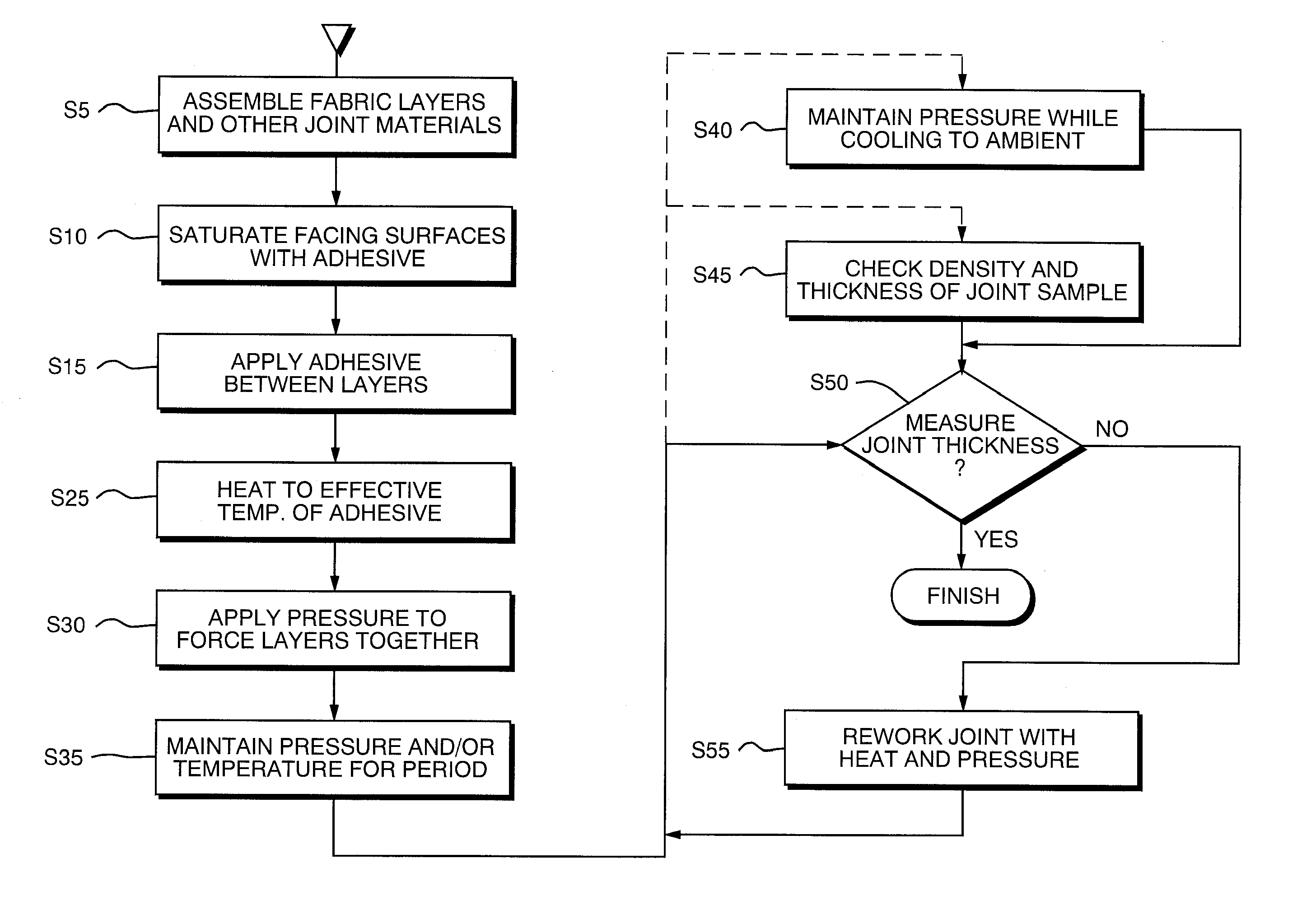
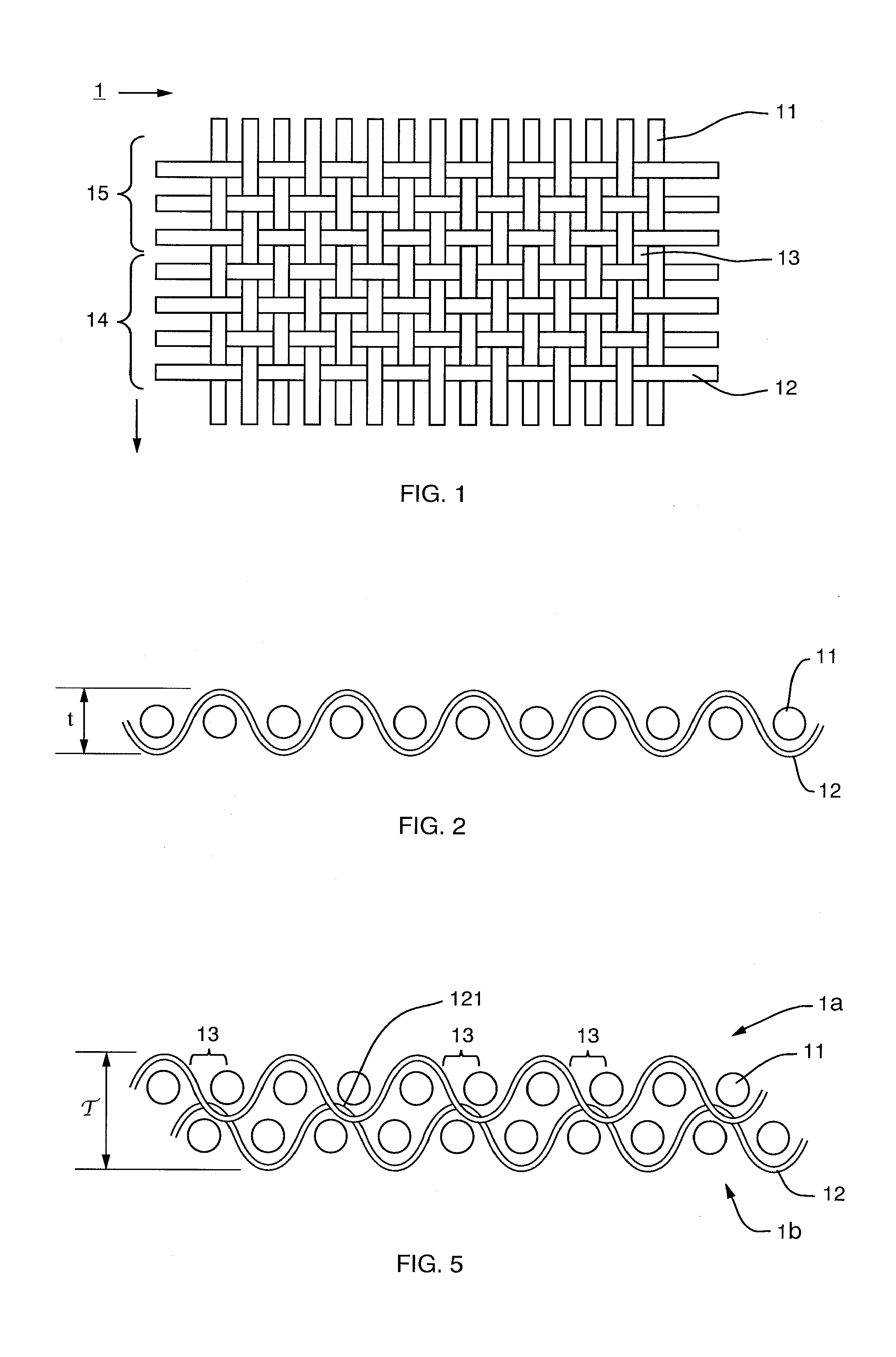
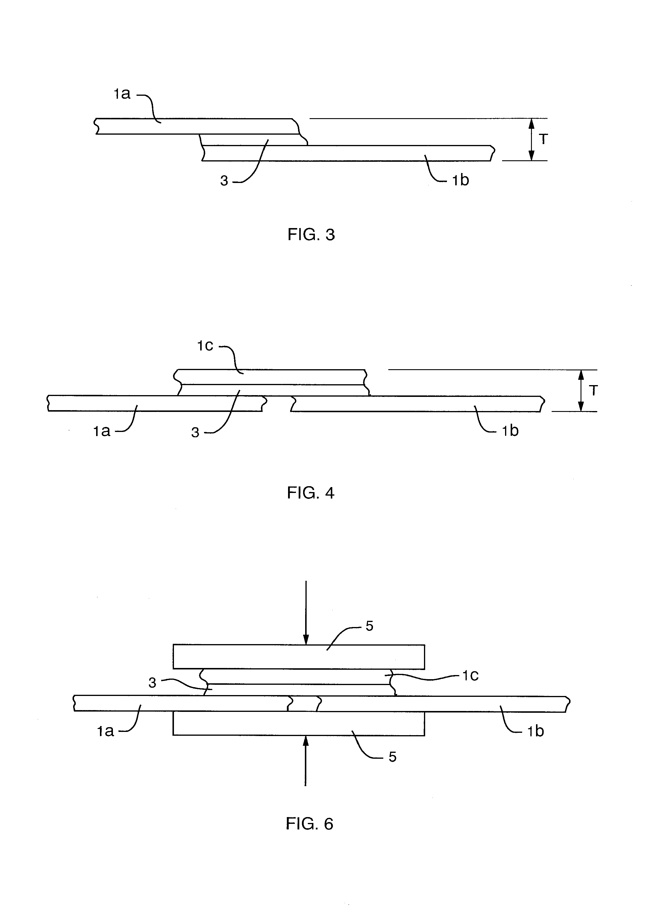
[0029]The invention provides a multi-layered, structural fabric and adhesive composite that is very useful as a creep resistant joint or seam connecting two sections of fabric, in particular high strength, gas-tight fabrics as may be used in airships and other critical applications, and a method for producing it. The fabric joint and method are particularly useful for joints used in high stress conditions and / or conditions in which the joint will be exposed to temperatures up to 140° F. for a prolonged period. The invention is also particularly useful with woven fabrics including fibers having a tenacity of 10 grams / denier or higher. However, the invention can be used with a variety of different types of fabrics, including a woven, knitted, composite or other fabrics, or other applications. In short, the method of the invention can be used to join two or more fabrics of any type or composition. The invention can also be used to form joints of any desired width and / or length, or for ...


PUM

PropertyMeasurementUnit
pressureaaaaaaaaaa
temperaturesaaaaaaaaaa
pressureaaaaaaaaaa

Abstract

A method for joining fabrics, particularly high strength fabrics such as airship hull fabrics, including the steps of: measuring selected parameters of two fabric layers to be joined and the adhesive and any tape or other materials intended to be included in the joint; calculating therefrom an optimal value of a quality control parameter of an ideal joint, such as joint thickness, specific gravity or opacity; assembling the two fabric layers and other materials in the desired order; and applying heat and pressure to the assemblage until the selected quality control parameter of the joint, such as joint thickness, specific gravity or opacity, is satisfied.

Description

[0001]This application relates and claims priority to pending U.S. application Ser. No. 60 / 442,104, filed Jan. 23, 2003.FIELD OF THE INVENTION [0002]This invention relates to forming high strength fabric joints, characterized as structural joints and used in fabric constructions for airship hulls, radomes, aerostats, tension roofs, and the like, by controlling joint forming process parameters such as heat, temperature, pressure, time, density, opacity, and joint thickness directly or by feedback mechanisms in order to insure the desired character and quality of joint. The invention is particularly useful in forming high strength joints between woven fabrics made of high tenacity, e.g., 10 g / denier fibers.BACKGROUND OF THE INVENTION [0003]Large inflatable devices and fabric structures, such as airship hulls, radomes, aerostats, tension roofs, all require large pieces of fabric, or composite materials including fabric layers, to be joined together, since a these structures cannot typi...

Claims


Application Information

Patent Timeline
Patent Type & Authority Patents(United States)
IPC IPC(8): B32B41/00B29C65/02B32B37/06B29C65/00B29C65/18B29C65/50B32B5/26B32B7/04
CPCB29C65/18B29C66/954B29C66/1122B29C66/1142B29C66/43B29C66/729B29C66/90B29C66/919B29C66/929B32B5/26B32B7/04B29C65/5021B29C65/483B29C65/4815B29C66/91411B29C66/91431B29C66/91935B29C66/9241B29C65/5042B29C66/949B29C65/485Y10T428/192Y10T428/19B29C66/832B29C65/8253B29C66/73132B32B7/12B32B2605/18B32B37/1207B32B2605/003B32B5/024
Inventor HOWLAND, CHARLES A
Owner WARWICK MILLS INC
Why Eureka
Try Eureka