
Hydrogen generation with efficient byproduct recycle

a byproduct recycling and hydrogen generation technology, applied in the direction of hydrogen separation using solid contact, electrochemical generators, chemistry apparatus and processes, etc., can solve the problems of reduced hydrogen production efficiency, reduced hydrogen utilization rate, and inability to use without further purification, so as to improve or optimize hydrogen, improve or optimize purity

Active Publication Date: 2007-03-20
GAS TECH INST +2
View PDF11 Cites 37 Cited by
  • Summary
  • Abstract
  • Description
  • Claims
  • Application Information

AI Technical Summary

Benefits of technology

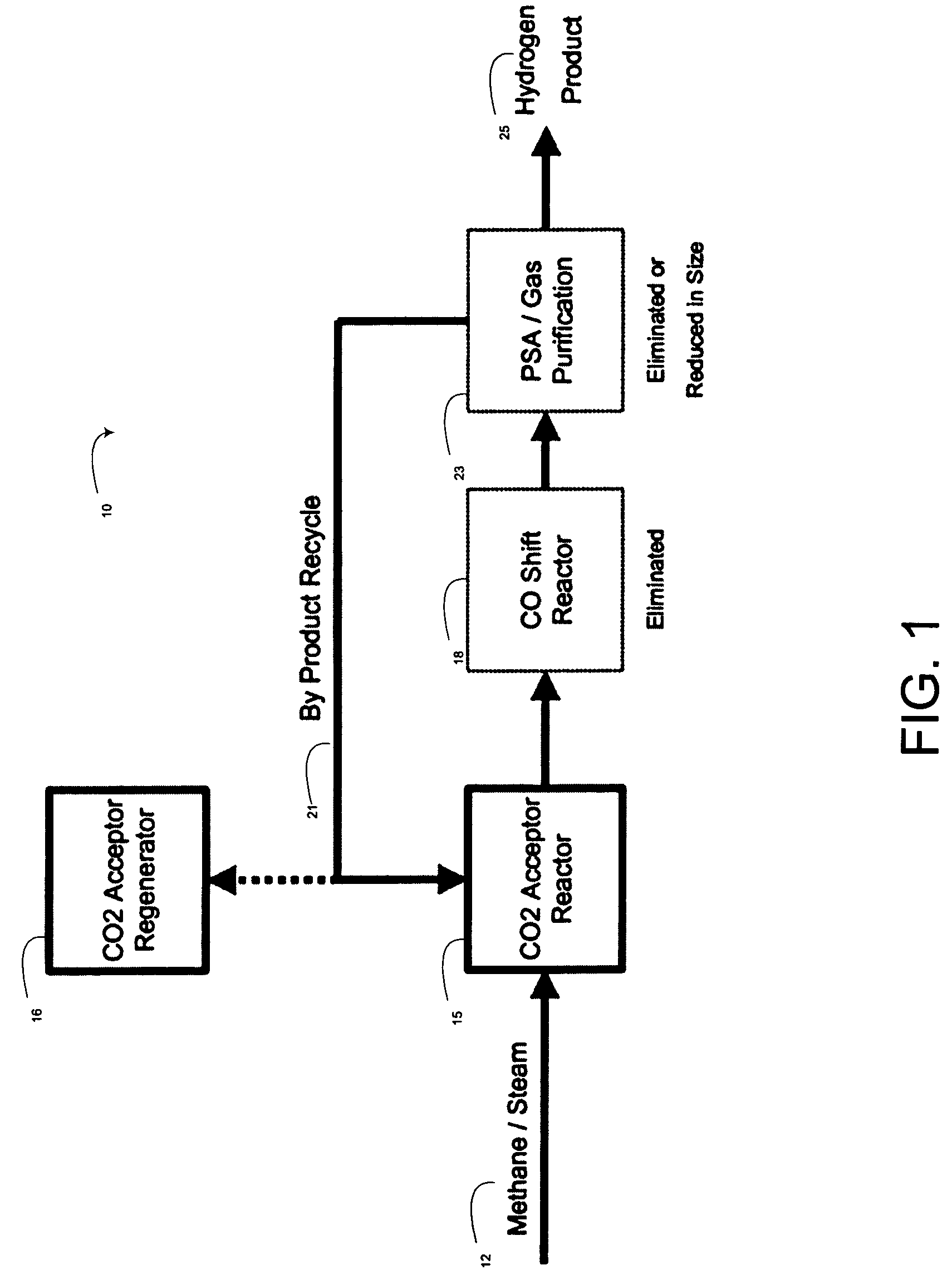
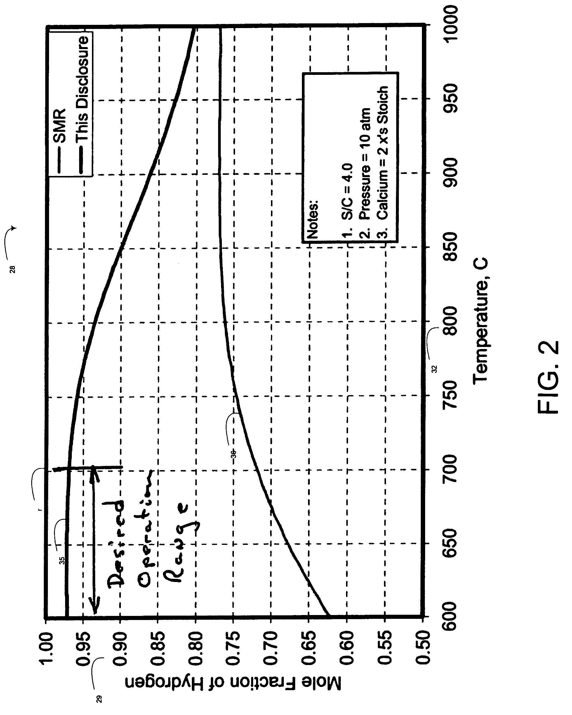
[0017]The present invention is directed to methods and systems for steam reforming of methane. Embodiments of the invention may advantageously improve or optimize the hydrogen produced in the product stream, and the methane produced in the by-product stream, by selectively heating the process. The improvement or optimization of hydrogen in the product stream and methane in the by-product stream, particularly in the presence of a pressure swing absorbent, may minimize the presence of gaseous oxides of carbon in the streams.

Problems solved by technology

Steam methane reformers, however, generally produce less than 90% pure hydrogen molecules in their product streams.
The presence of the bi-products pollutes the hydrogen stream making it unusable without further purification.
The reaction is equilibrium limited and is highly endothermic requiring heat input of 60 Kcal / mol CH including the heat needed to produce steam from liquid water.
The shift reaction is a costly unit of production, requiring significant equipment and operating costs.
Shift reactors have been required to “scrub” the product stream of gas, because the conventional steam reforming reaction only produces about 75% of the potential hydrogen yield in the feedstock and leaves unshifted carbon monoxide in the product gas stream.
Unshifted carbon monoxide and product carbon dioxide will generally be detrimental to most chemical reactions using the product hydrogen.
In addition to being expensive, the purification process using PSAs results in loss of hydrogen product that must be rejected with the non-hydrogen stream that is produced.
The conventional steam reformation of methane may also produce too many oxides of carbon in the product gas stream.

Method used


Image

  • Hydrogen generation with efficient byproduct recycle
  • Hydrogen generation with efficient byproduct recycle
  • Hydrogen generation with efficient byproduct recycle

Examples


Embodiment Construction

[0025]The present invention relates to methods and systems for generating hydrogen using reforming catalysts together with CO2 gas absorbents. Many specific details of certain embodiments of the invention are set forth in the following description and in FIGS. 1–5 to provide a thorough understanding of such embodiments. One skilled in the art, however, will understand that the present invention may have additional embodiments, or that the present invention may be practiced without several of the details described in the following description.

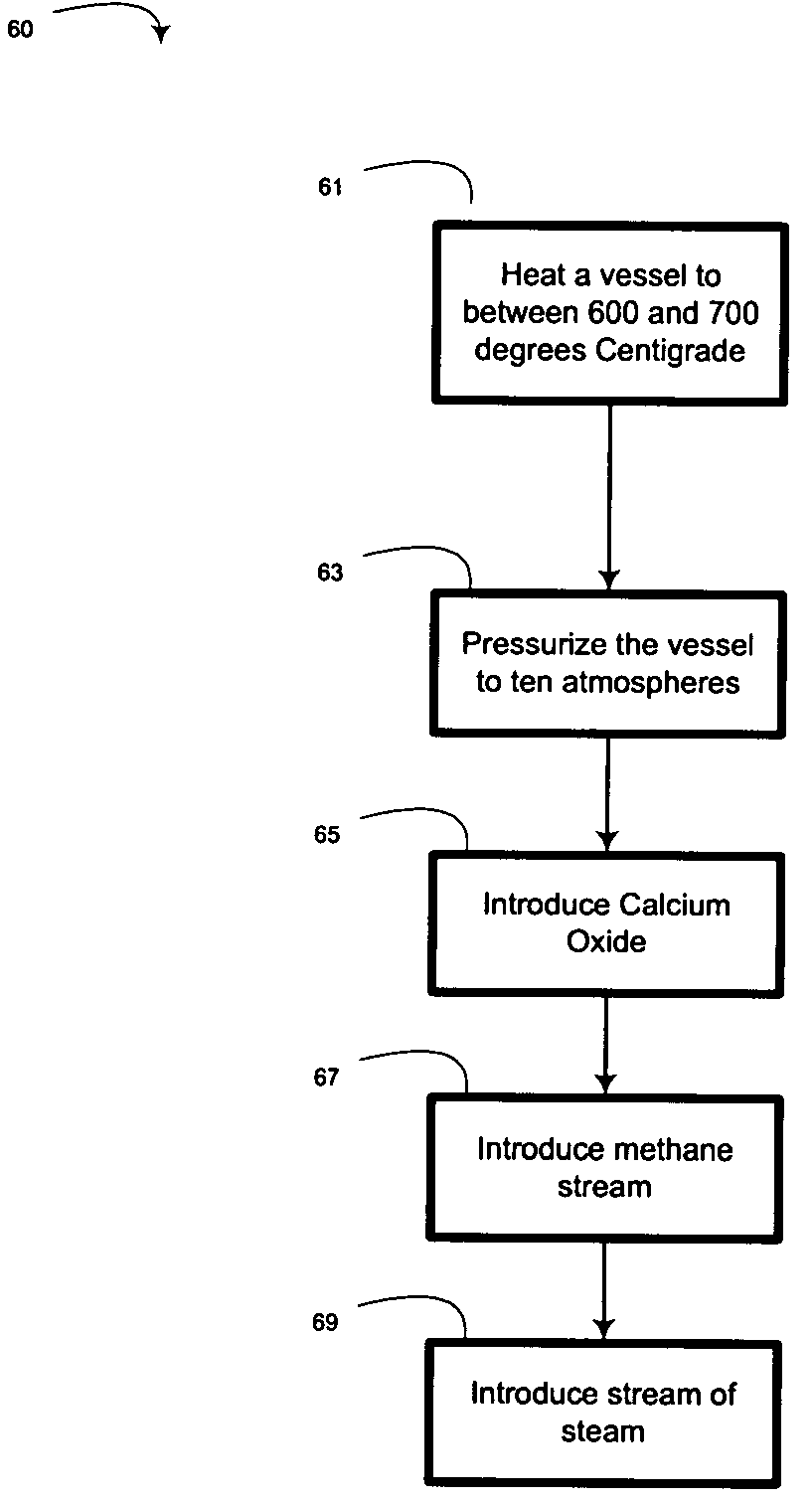
[0026]By way of overview, methods and systems for generating hydrogen gas from methane are provided. In one embodiment, a method includes heating a vessel containing a catalyst to a temperature of between 600° centigrade to 700° centigrade, and pressurizing the vessel to about ten atmospheres. A pressure swing absorbent (PSA), a methane stream, and a stream of steam are introduced into the vessel. A resulting stream of product hydrogen, and a by...


PUM

PropertyMeasurementUnit
pressureaaaaaaaaaa
pressuresaaaaaaaaaa
mole fractionaaaaaaaaaa

Abstract

Methods and systems for generating hydrogen gas from methane are disclosed. In one embodiment, a method includes heating a vessel containing a catalyst to a temperature above approximately 600° centigrade and pressurizing the vessel to about ten atmospheres. A pressure swing absorbent, a methane stream, and a stream of steam are introduced into the vessel. In a particular aspect, the temperature may be maintained within a range of approximately 600 C. to approximately 700 C.

Description

RELATED APPLICATIONS[0001]This application incorporates by this reference a co-pending, commonly-owned application by the same inventor entitled “Hydrogen Generation Apparatus and Method” filed on Oct. 15, 2002 with Ser. No. 10 / 271,406.FIELD OF THE INVENTION[0002]This invention relates generally to production of hydrogen molecules and, more specifically, to use of CO2 adsorbents.BACKGROUND OF THE INVENTION[0003]Hydrogen is a very common atom occurring in many fuels, often in the presence of carbon in organic compounds. Generally, hydrogen may be used for upgrading petroleum feed stock to more useful products. In addition, hydrogen is used in many chemical reactions, such as reducing or synthesizing compounds. Particularly, hydrogen is used as a primary chemical reactant in the production of useful commercial products, such as cyclohexane, ammonia, and methanol.[0004]Hydrogen itself is quickly becoming a fuel of choice because it reduces green house emissions. Particularly, hydrogen ...

Claims


Application Information

Patent Timeline
Patent Type & Authority Patents(United States)
IPC IPC(8): C01B3/26B01J7/00C01B3/38C01B3/56
CPCC01B3/38C01B3/56C01B2203/0233C01B2203/148C01B2203/0425C01B2203/0475C01B2203/0283
Inventor STEWART, ALBERT E.
Owner GAS TECH INST
Learn More