Load control circuit and method for achieving reduced acoustic noise

a load control and acoustic noise technology, applied in the direction of automatic control, process and machine control, instruments, etc., can solve the problems of increasing the complaints of acoustic noise of customers operating such lamps, insufficient solution, and inability to reduce acoustic noise, etc., to achieve the effect of reducing acoustic nois

Active Publication Date: 2007-03-20
LUTRON TECH CO LLC
View PDF16 Cites 14 Cited by
  • Summary
  • Abstract
  • Description
  • Claims
  • Application Information

AI Technical Summary

Benefits of technology

[0019]It is an object of the present invention to provide an improved load control circuit, for example, a dimmer circuit, that reduces acoustic noise, particularly when used with MLV lamp loads.
[0021]The objects of the invention are achieved by a load control circuit comprising a bidirectional semiconductor switch for switching at least a portion of both positive and negative half cycles of an alternating current source waveform to a load, the bidirectional semiconductor switch having a control electrode, further comprising a phase angle setting circuit including a timing circuit which sets the phase angle during each half cycle of the AC source waveform when the bidirectional semiconductor switch conducts; the phase angle setting circuit including a voltage threshold trigger device connected in series with the control electrode of the switch, further comprising a rectifier bridge connected in series between an output of the timing circuit and the control electrode of the semiconductor switch, and wherein the rectifier bridge has a first pair of terminals and a second pair of terminals, the first pair of terminals connected in series between the output of the timing circuit and the control electrode of the semiconductor switch, and the second pair of terminals connected to the voltage threshold trigger device, whereby acoustic noise generated in the load connected in series with the load control circuit is reduced.
[0022]The objects of the invention are also achieved by a method for reducing acoustic noise generated in an electrical load driven by a phase-cut load control circuit from an AC source waveform, the method comprising setting a phase angle during each half cycle of the AC source waveform when a bidirectional semiconductor switch conducts, providing a voltage threshold trigger device connected in series with a control electrode of the switch, whereby control electrode current is provided to the switch when a threshold voltage is exceeded, further comprising providing the control electrode current to the switch such that the control electrode current flows in only one direction through the voltage threshold trigger device, thereby to reduce asymmetry in the control electrode current and contribute to reduced acoustic noise in the load.
[0023]The objects of the invention are also achieved by a load control circuit having first and second terminals for connection in series with a controlled load, the load control circuit comprising a bidirectional semiconductor switch for switching at least a portion of both positive and negative half cycles of an alternating current source waveform to a load, the bidirectional semiconductor switch having a control electrode, further comprising a phase angle setting circuit including a timing circuit which sets the phase angle during each half cycle of the AC source waveform when the bidirectional semiconductor switch conducts, the phase angle setting circuit including a voltage threshold trigger device connected in series with the control electrode of the switch, further comprising a first circuit connected between the timing circuit and the control electrode of the semiconductor switch for insuring that current flowing through the voltage threshold trigger device flows in only one direction, and wherein the first circuit has a first pair of terminals and a second pair of terminals, the first pair of terminals connected in series between an output of the timing circuit and the control electrode of the semiconductor switch, and the second pair of terminals connected to the voltage threshold trigger device, whereby acoustic noise generated in the load connected in series with the load control circuit is reduced.

Problems solved by technology

There has been an increase in complaints about acoustic noise by customers operating such lamps.
Acoustic noise has always been an issue with magnetic low-voltage (MLV) loads.
However, this solution has proved inadequate in view of the above factors now often present in the implementation of low-voltage lighting.
This is particularly a problem when the transformer has little or no air gap, such as is true of toroidal transformers.
The prior art devices of FIGS. 1 and 2A have been known to cause excessive acoustic noise to be generated in a load, such as an MLV lamp load, comprising a transformer-supplied low-voltage lamp, when such a load is coupled to the output of the dimmer.
It is believed that this asymmetry causes the transformer to saturate, thereby increasing acoustic noise.
In this case, a lamp debuzzing coil or choke will be unable to eliminate acoustic noise from the transformer, resulting from asymmetry in the output voltage, because the coil or choke does not eliminate the net DC component.

Method used


Image

  • Load control circuit and method for achieving reduced acoustic noise
  • Load control circuit and method for achieving reduced acoustic noise
  • Load control circuit and method for achieving reduced acoustic noise

Examples


Embodiment Construction

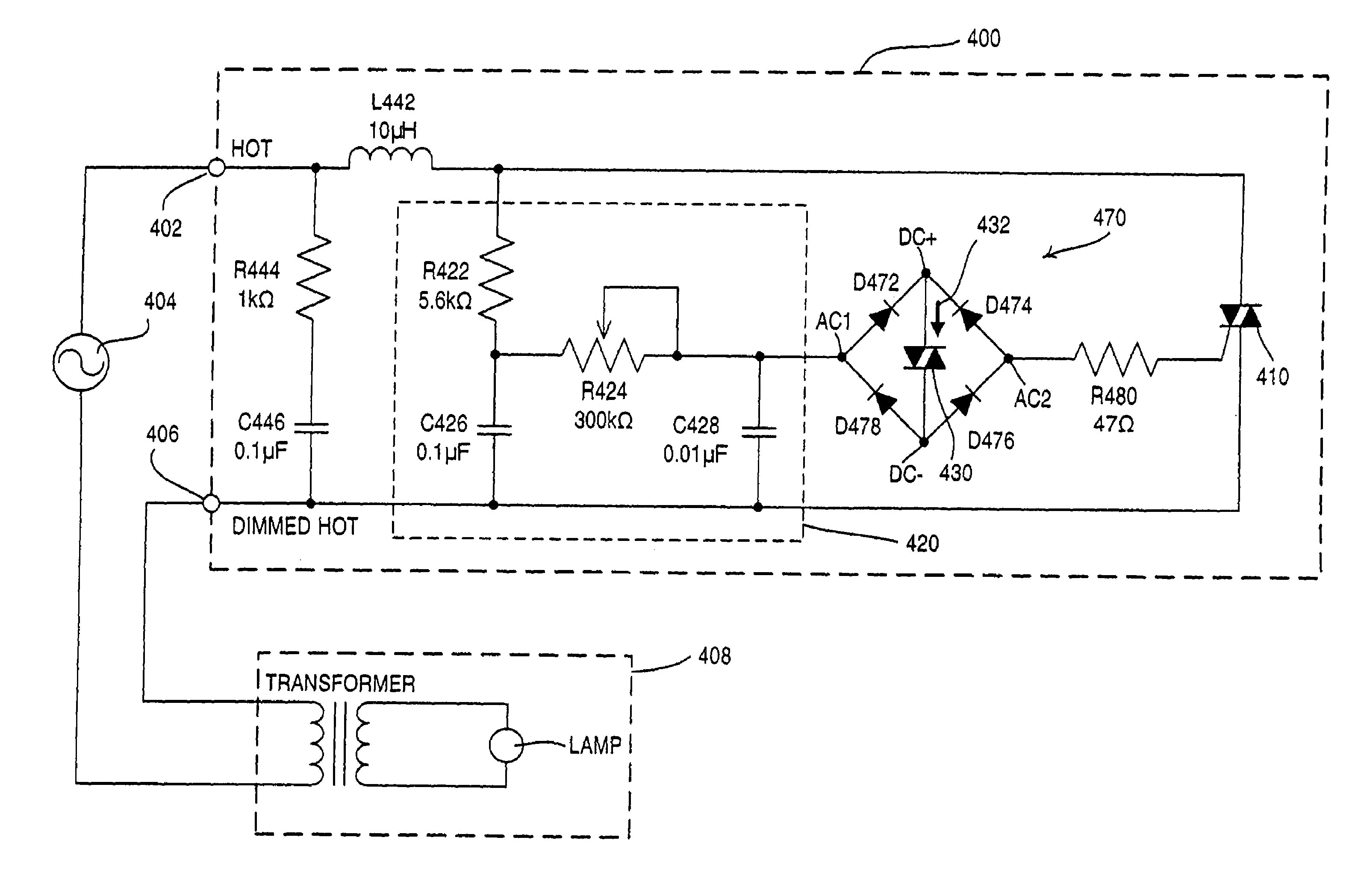
[0041]With reference now to the drawings, FIG. 4A shows an improved load control circuit, and, in particular, a dimmer circuit 400, according to the present invention, for reducing acoustic noise. The hot side of the AC supply 404 is generally connected to a HOT terminal 402, and one side of the primary winding of the transformer driving the lamp load is typically connected to a DIMMED HOT terminal 406. The dimmer circuit includes a noise / EMI filter circuit comprising an inductor L442, a resistor R444, and a capacitor C446. Resistor R422, potentiometer R424, and capacitors C426, C428 form a double-phase-shift RC timing circuit 420 in which the time constant is variably set by the potentiometer R424 thereby changing the time over which capacitor C428 charges. The rate of charge of capacitor C428 will in turn change the phase angle of the AC waveform at which the bidirectional semiconductor switch (triac 410) conducts once the threshold of the trigger device (diac 430) is exceeded.

[00...


PUM


Abstract

A load control circuit having first and second terminals for connection in series with a controlled load comprises a bidirectional semiconductor switch for switching at least a portion of both positive and negative half cycles of an alternating current source waveform to the load. The bidirectional semiconductor switch has a control electrode. The load control circuit includes a phase angle setting circuit, including a timing circuit, which sets the phase angle during each half cycle of the AC source waveform when the bidirectional semiconductor switch conducts. The phase angle setting circuit includes a voltage threshold trigger device connected in series with the control electrode of the switch. The phase angle setting circuit further comprises a rectifier bridge connected in series between an output of the timing circuit and the control electrode of the semiconductor switch, wherein the rectifier bridge has a first pair of terminals and a second pair of terminals, the first pair of terminals connected in series between an output of the timing circuit and the control electrode of the semiconductor switch, and the second pair of terminals connected to the voltage threshold trigger device. The load control circuit further includes an impedance in series electrical connection with the semiconductor switch control electrode. Acoustic noise generated in the load connected in series with the load control circuit is reduced, particularly when the load is a toroidal transformer driving a magnetic low voltage lamp and the load control circuit is a two-wire dimmer.

Description

BACKGROUND OF THE INVENTION[0001]The present invention relates to load control circuits, for example, lamp dimming circuits, and in particular, to an improved load control circuit for reducing acoustic noise, particularly in connection with dimming control of transformer-supplied lighting loads. The invention can also be used to control the speed of electrical motors for applications such as fans, motorized window treatments, and electrical tools, such as drills, grinders, and sanders.[0002]Low-voltage lighting, for example, halogen lighting, has come into increased use in recent years. These lamps operate on low voltages, for example 12 volts or 24 volts, and accordingly, a transformer is employed to reduce the normal line voltage to the low voltage necessary to operate the lamps.[0003]There has been an increase in complaints about acoustic noise by customers operating such lamps. The acoustic noise is believed to result from a number of factors including: the use of low-profile tr...

Claims


Application Information

Patent Timeline
Patent Type & Authority Patents(United States)
IPC IPC(8): G05B24/02G05F1/40H02M5/00
CPCH05B39/08
Inventor WEIGHTMAN, RUSSELL
Owner LUTRON TECH CO LLC
Why Eureka
Try Eureka