Fast plant test for model-based control

a plant test and model-based control technology, applied in the field of open-loop testing and system identification, can solve the problems of not having a great deal of choice among different perturbation signal designs, many signal design issues do arise, and other types of periodic signals have found little application

Inactive Publication Date: 2007-03-20
AIR PROD & CHEM INC
View PDF8 Cites 22 Cited by
  • Summary
  • Abstract
  • Description
  • Claims
  • Application Information

AI Technical Summary

Benefits of technology

[0018]A simplified model of the system responses for the system outputs is determined based on: the system settling time; the steady-state gains corresponding to the plurality of system outputs with respect to the system inputs; and linear dynamics of at least one predetermined order. The effect of the excitation of the input channels via the BMF signals on the system outputs is then simulated using this simplified system model and the resulting simulated responses are judged based on the plant-friendliness criteria. If the simulated system responses are judge

Problems solved by technology

Under these circumstances, there is not usually a great deal to choose among different perturbation signal designs.
However, this is quite an idealized situation in many applications and, in practice, many signal design issues do arise.
Other types of periodic signals have found little application so far given that they cannot be easily generated using shift register circuitry.
However, there are no examples in which models obtained with different input signals are compared and the strengths and weaknesses of the different perturbation signal designs are emphasized.
This means that a model with poor dynamic properties may be obtained.
The plant testing time estimate for MPC, Ttest, may become prohibitively long for systems with long process settling time and/or large nu

Method used


Image

  • Fast plant test for model-based control
  • Fast plant test for model-based control
  • Fast plant test for model-based control

Examples


Embodiment Construction

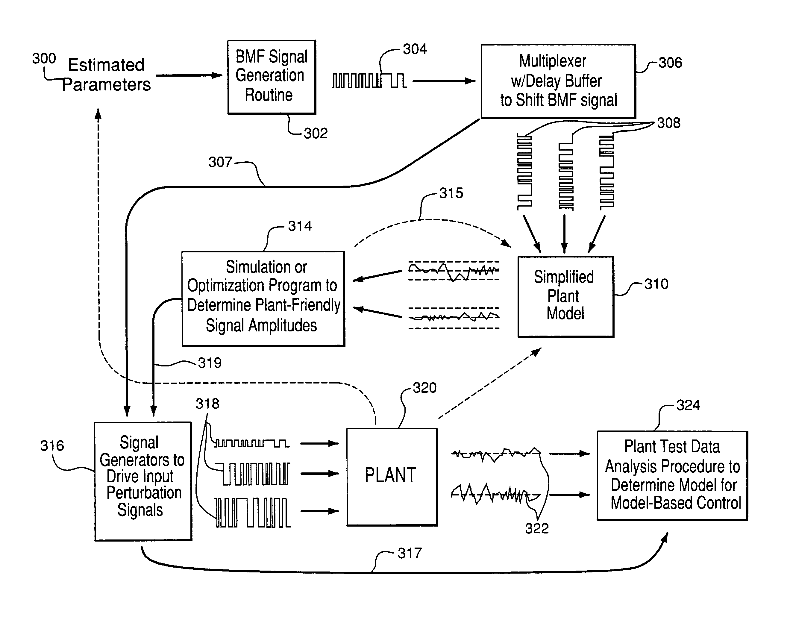
[0038]The present invention involves the design of a fast plant test to obtain a system model for model-based control of a system, such as an air separation unit (ASU), hydrogen carbon monoxide (HyCO) facility, or a natural gas liquefaction (LNG) plant, which has multiple input (manipulated) channels and multiple output (controlled) channels. An exemplary system is shown as plant 320 in FIG. 3. It is understood that other chemical plants, such as petro-chemical plants, or other complex systems, including electronic and mechanical systems, to be desirably operated via a model-based controller may also be tested according to the present invention.

[0039]One important consideration in such a test is the generation of perturbation signals used to test the response of the system to perturbation of its input levels. Perturbation Signals for System Identification, edited by K. Godfrey, Prentice Hall International, Ltd., 1994, provides general background on perturbation signal design for mod...


PUM


Abstract

A method and apparatus for designing perturbation signals to excite a number of input variables of a system, in order to test that system for the purpose of obtaining models for the synthesis of a model-based controller. The method begins with providing input parameters of the system. A plurality of binary multi-frequency (BMF) signals are generated based on these input parameters and the frequency spectra of these BMF signals are calculated. One BMF signal is selected out of the set of BMF signals so that the frequency spectrum of the selected BMF signal most closely matches a desired frequency spectrum specified by the input parameters. The selected BMF signal is used as a first perturbation signal for testing the system. The selected BMF signal is also shifted by predetermined amounts of samples to create delayed copies of the original BMF signal to be used as additional perturbation signals.

Description

BACKGROUND OF THE INVENTION[0001]The present invention relates to a method and apparatus for open-loop testing and system identification to generate models of a system for model-based control of the system. More specifically, the present invention relates to a method of system identification of a multivariable nature using plant-friendly binary multi-frequency signals, in conjunction with multivariable parametric modeling techniques, to achieve significant time savings in testing time.[0002]One method of characterizing the dynamics of a system is to apply perturbation signals at the input channels and measure the response of the system to these signals. The input and output signals are then processed to give an estimate of the dynamics of the system. This procedure is known as system identification.[0003]In much of the literature and prior art on system identification, little attention has been paid to the design of the perturbation signal itself, other than to the fact that the sig...

Claims


Application Information

Patent Timeline
IPC IPC(8): G05B13/02G01D3/00G01M19/00G01P21/00G06Q50/00G01M99/00G01R31/28G05B13/04G05B23/00G05B23/02G06F19/00H03K3/00H03K3/84
CPCG05B17/02
Inventor KOTHARE, SIMONE L.MANDLER, JORGE ANIBAL
Owner AIR PROD & CHEM INC
Why Eureka
Try Eureka