On-site analysis system with central processor and method of analyzing

a technology of analysis system and analyzer, applied in the field of material processing, can solve the problem that analytical instruments do not generate values

Inactive Publication Date: 2007-03-20
EUROFINS QTA
View PDF128 Cites 82 Cited by
  • Summary
  • Abstract
  • Description
  • Claims
  • Application Information

AI Technical Summary

Benefits of technology

[0019]The present invention is directed to a process for identifying and quantifying one or more properties of interest of a material, the process involving providing a material to be analyzed; providing one or more data acquisition devices capable of acquiring data for prediction of one or more properties of the material; providing a central processor capable of computing one or more predicted results using multivariate calibration models and storing a database of multivariate calibration models; providing a communication link between data acquisition devices and the central processor; and analyzing the material using the data acquisition devices and the central processor in order to obtain results on one or more properties of interest. Preferably the central processor stores at least a portion of either measurement data, measurement results, or both. Preferably the data acquisition devices are capable of being transported from site to site. The calibration model is multivariate, and compensates for an effectively comprehensive set of measurement conditions and secondary material characteristics. Preferably, the communication link is capable of providing resultant information from the central processor to a user interface in the vicinity of the sensor. However, the resultant information may be conveyed by other means, such as by telephone communication, or may be conveyed by the same type of communication link as available between data acquisition device and central processor but to a location removed from the data acquisition device.

Problems solved by technology

Analytical instruments do not generate the values of a property of interest directly.

Method used


Image

  • On-site analysis system with central processor and method of analyzing
  • On-site analysis system with central processor and method of analyzing
  • On-site analysis system with central processor and method of analyzing

Examples


example 1

[0196]A feasibility study was done to determine if a property model could be developed to measure the concentration of squalane in squalene. In accordance with block 70 of FIG. 4, the method was defined as FT-NIR using the MATRIX Model F instrument manufactured by Bruker Optics, with sample presentation for liquid samples provided by closure caps with dimensions of 18-mm diameter×10-mm high manufactured by Cincinnati Container Corporation. The objectives for the property model included measurements of squalane in squalene having concentrations ranging from trace amounts to about 10 weight percent with a limit of desired precision of 0.10% or smaller as measured by RMSEP. The objectives further indicated that the measurements will be taken by non-skilled operators who will dispense about 1 mL of liquid samples into separate, disposable caps, and the sample temperature may vary from about 0° C. to 60° C. In accordance with the block 72 of FIG. 4, the expected range of the concentratio...

example 2

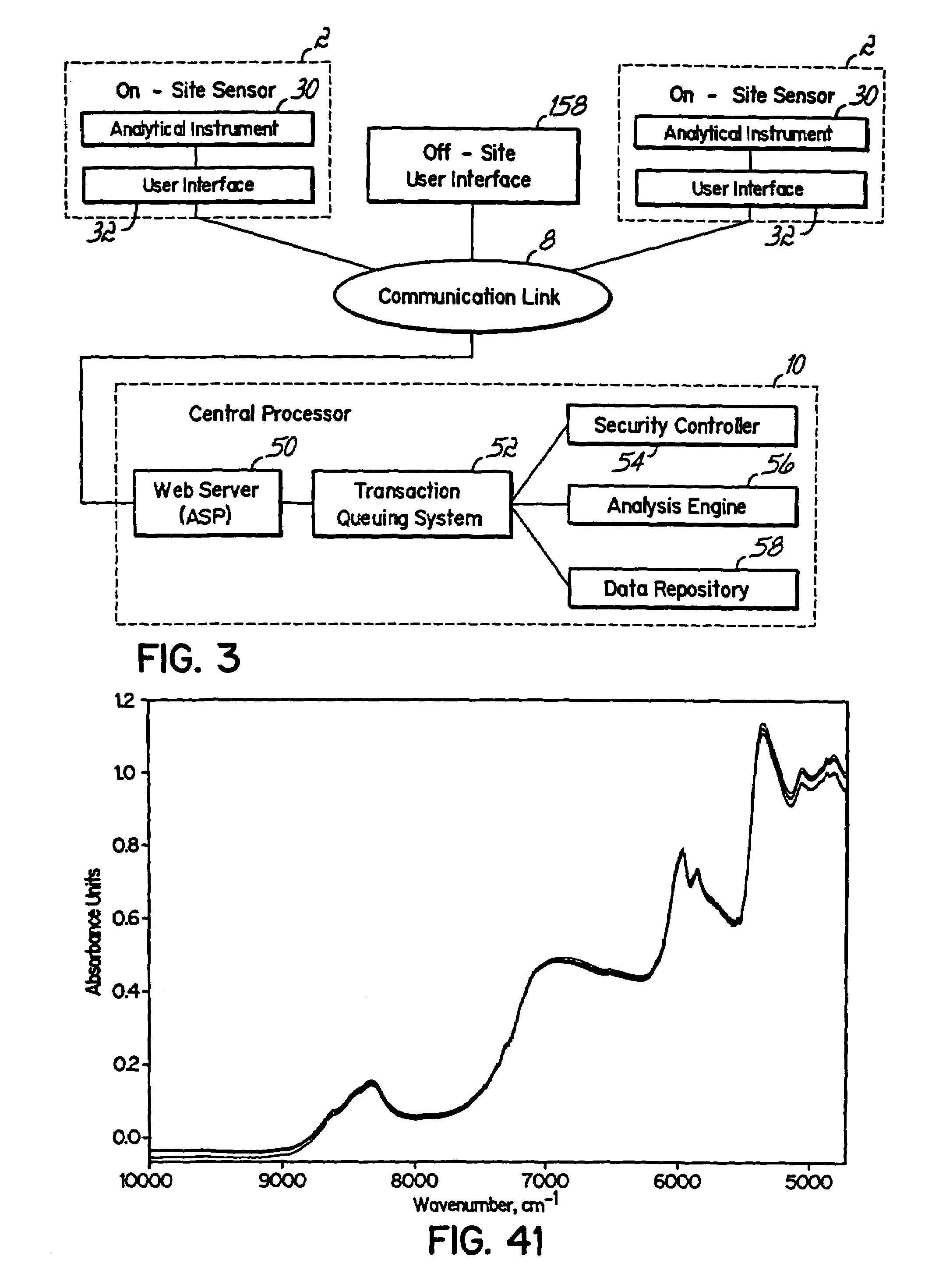
[0205]The light intensity of the environment is a potentially influential factor (block 84). The lights are expected to be either on or off. To determine if a difference in the intensity of background light in the room will affect the concentrations predicted by Model 1.1 (block 88), the spectrum of a single sample with an observed value of 2.00% of squalane in squalene was acquired four times with the overhead fluorescent room lights on and four times with the lights off without changing any other measurement conditions. FIG. 10 shows the superposition of the resulting eight spectra. Since no measurable differences are observed between the spectra, variations in the light intensity of this particular environment will not affect the predicted concentrations.

[0206]To further demonstrate that the light intensity is not an influential factor, Model 1.1 was used to compute predicted values of the concentrations corresponding to each of the eight spectra for the 2.00% squalane samples. A...

example 3

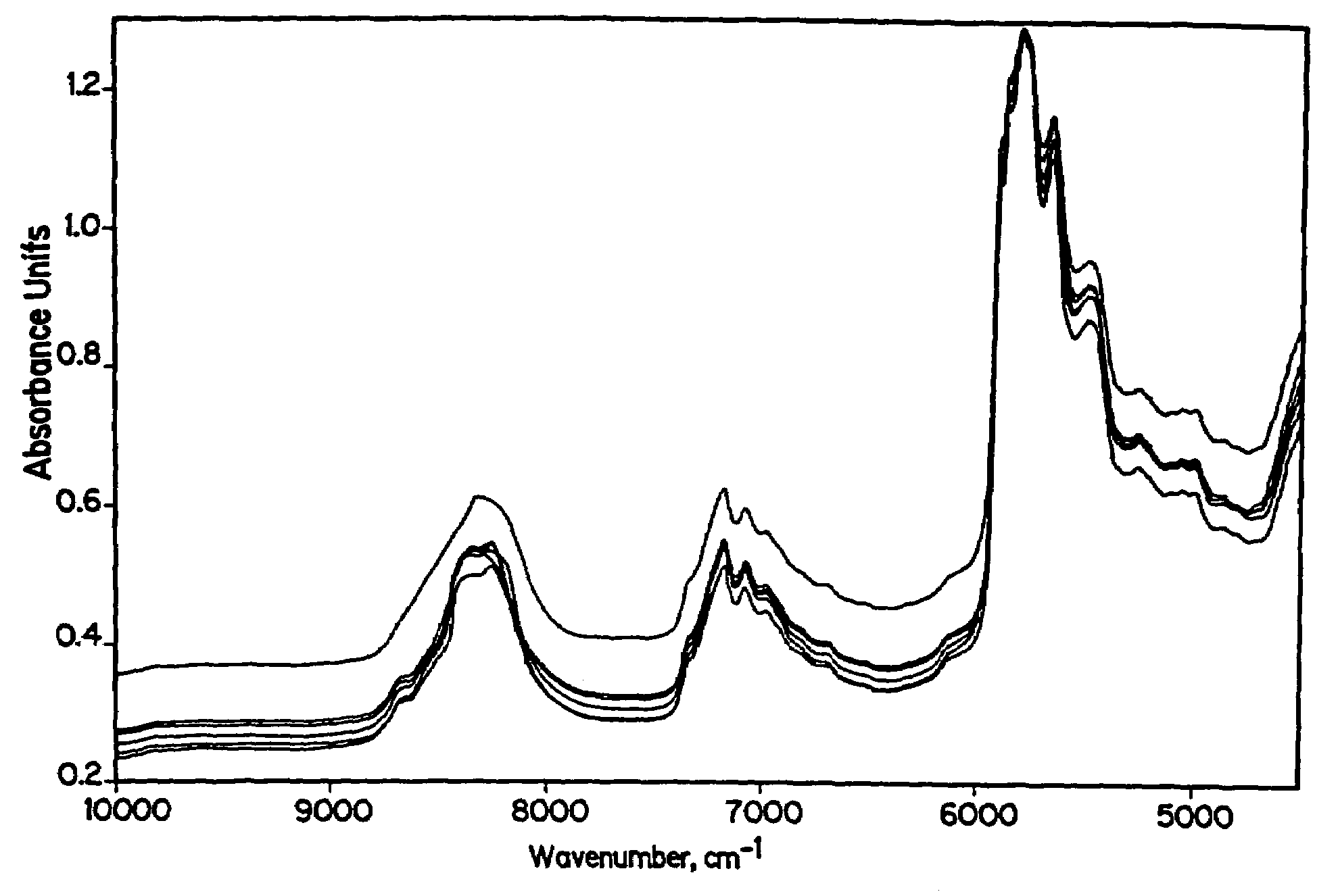
[0208]The orientation of the sample cap is a potentially influential factor (block 84). The orientations are expected to be random. To determine if variation in the orientation of the sample cap (block 86) will affect the predicted concentrations (block 88), a sample of 1.00% of squalane in squalene was prepared and measured with four different cap orientations. The initial orientation of the cap was selected at random, and additional orientations were attained by successively rotating the cap by approximately 90 degrees about an axis perpendicular to the bottom of the cap between measurements. As shown in FIG. 11, measurable differences were observed in these spectra, indicating that orientational variance is probably an influential factor.

[0209]The six calibration samples in the training set of Example 1, each with a sample cap orientation labeled as orientation 1, were then measured with three additional orientations selected at random, labeled as orientations 2, 3, and 4, each r...


PUM

PropertyMeasurementUnit
humidityaaaaaaaaaa
diameteraaaaaaaaaa
temperatureaaaaaaaaaa

Abstract

A method of analysis, analysis system, program product, apparatus, and method of supplying analysis of value incorporating the use of at least one data acquisition device, a central processor, and a communication link that is connectable between the data acquisition device and the central processor. The central processor is loaded with multivariate calibration models developed for predicting values for various properties of interest, wherein the calibration models are capable of compensating for variations in an effectively comprehensive set of measurement conditions and secondary material characteristics. As so configured, the calibration models can compensate for instrument variance without instrument-specific calibration transfer. Measurement results generated by the central processor can be transmitted to an output device of a user interface.

Description

CROSS-REFERENCE TO RELATED APPLICATIONS[0001]This application claims the benefit of two U.S. Provisional Patent Applications, Ser. Nos. 60 / 307,347 and 60 / 307,348, both filed on Jul. 23, 2001, the disclosures of which are incorporated by reference herein. This application is also related to U.S. patent application Ser. No. 10 / 188,853, filed on even date herewith by James Thomas Kent, et al., entitled “EXTENSIBLE MODULAR COMMUNICATION EXECUTIVE WITH ACTIVE MESSAGE QUEUE AND INTELLIGENT MESSAGE PRE-VALIDATION,” the disclosure of which is incorporated by reference herein.STATEMENT REGARDING FEDERALLY SPONSORED RESEARCH OR DEVELOPMENT[0002]Not applicable.FIELD OF THE INVENTION[0003]The present invention is generally directed to a process for analyzing materials, preferably at multiple locations. More particularly, the present invention relates to a method of rapid analysis which utilizes analytical instrumentation, for example spectroscopic sensor units, on site to transmit and receive i...

Claims


Application Information

Patent Timeline
Patent Type & Authority Patents(United States)
IPC IPC(8): G06F15/00G01N21/27G01N35/00
CPCG01N21/274G01N21/359G01N35/00712G01N35/00871G01N2201/12792G01N2035/00881G01N2201/12753
Inventor LUNDSTEDT, ALAN P.HALL, ALLEN L.TSENG, CHING-HUI
Owner EUROFINS QTA
Why Eureka
Try Eureka