Eureka AIR delivers breakthrough ideas for toughest innovation challenges, trusted by R&D personnel around the world.

Micro electromechanical systems for delivering high purity fluids in a chemical delivery system

Inactive Publication Date: 2007-03-27
AIR LIQUIDE AMERICA INC +1
View PDF25 Cites 28 Cited by
  • Summary
  • Abstract
  • Description
  • Claims
  • Application Information

AI Technical Summary

Benefits of technology

[0018]It is another object of the present invention to provide a chemical distribution system employing MEMS components and having a high degree of reliability and enhanced performance.
[0024]In a further aspect of the present invention, an integrated flow meter and internal purge system includes a first shut-off valve in fluid communication with a main flow path of the system to selectively control input of a fluid into the system from a fluid supply source, a second shut-off valve in fluid communication with the main flow path to selectively control output of the fluid from the system to a delivery site, and a flow meter. The flow meter includes a sensor in fluid communication with the main flow path and disposed between the first and second shut-off valves, and a control valve in fluid communication with the main flow path and disposed between the first and second shut-off valves. The sensor measures a physical property of the fluid flowing through the main flow path, and the control valve selectively controls the flow rate of the fluid flowing through the main flow path based upon measurements of the sensor.

Problems solved by technology

Many of these chemicals can be easily contaminated (e.g., by exposure to air, particulate material, moisture, etc.) in the system distribution lines, resulting in reduced production yields or the formation of solids that may become embedded within and even clog distribution lines.
In addition, many of the chemicals utilized in the distribution lines are toxic and / or present a fire hazard or explosion risk.
However, such conventional components are less desirable when system size becomes an issue, particularly, when dealing with very low volumetric flows, e.g., 20 cubic centimeters per minute (ccm) or less.
As the number of components (e.g., valves, sensors, mass flow controllers, etc.) increases, integration of conventional connectors and tubing into complex chemical distribution systems, not to mention conventional electronics control blocks (typically controlled by conventional programmable logic controllers), becomes cumbersome and quite expensive as well as requiring additional floor space to house the system.
Further, these distribution systems are difficult to operate and control, as most individual components require dedicated control lines (electrical or pneumatic) and are more prone to contamination due to the increased system volume and the increasing difficulties associated with cleaning, purging and evacuating distribution lines within the system.
However, despite the advantages associated with employing MEMS, there has been a reluctance to utilize MEMS in high purity chemical distribution systems due to certain problems associated with MEMS components.
In particular, MEMS shut-off valves, an important component in any fluid distribution system design, presently do not have sufficient sealing characteristics that would render such valves useful for complex distribution systems.
The problem associated with the cantilever-type design for MEMS shut-off valves is that they possess an asymmetrical sealing characteristic.
Further, the integration of too many MEMS components into a single die may result in a reduced reliability and flexibility of the distribution system, where undesirable interactions or interference may occur between different sensors or actuators associated with the die.
In addition, the scaling of common types of fluid controllers into MEMS components can present problems.
For example, the use of conventional MEMS mass flow controllers often becomes unreliable and presents quality issues, particularly in high purity chemical distribution applications, due to partial or even complete clogging of micro-channels or orifices that can occur during use of the mass flow controller.
Frequently, such clogging and contamination problems occur when operation of the mass flow controller is halted for a period of time, resulting in residual and stagnant chemical fluid within the system block.
However, enlarging the size of the MEMS system diminishes the advantages associated with utilizing MEMS technology.
Thus, the integration of MEMS valves and other MEMS components into complex and miniature high purity fluid distribution systems is difficult and is not as simple as combining conventional, non-MEMS components together to form a particular chemical flow configuration.

Method used


Image

  • Micro electromechanical systems for delivering high purity fluids in a chemical delivery system
  • Micro electromechanical systems for delivering high purity fluids in a chemical delivery system
  • Micro electromechanical systems for delivering high purity fluids in a chemical delivery system

Examples


Embodiment Construction

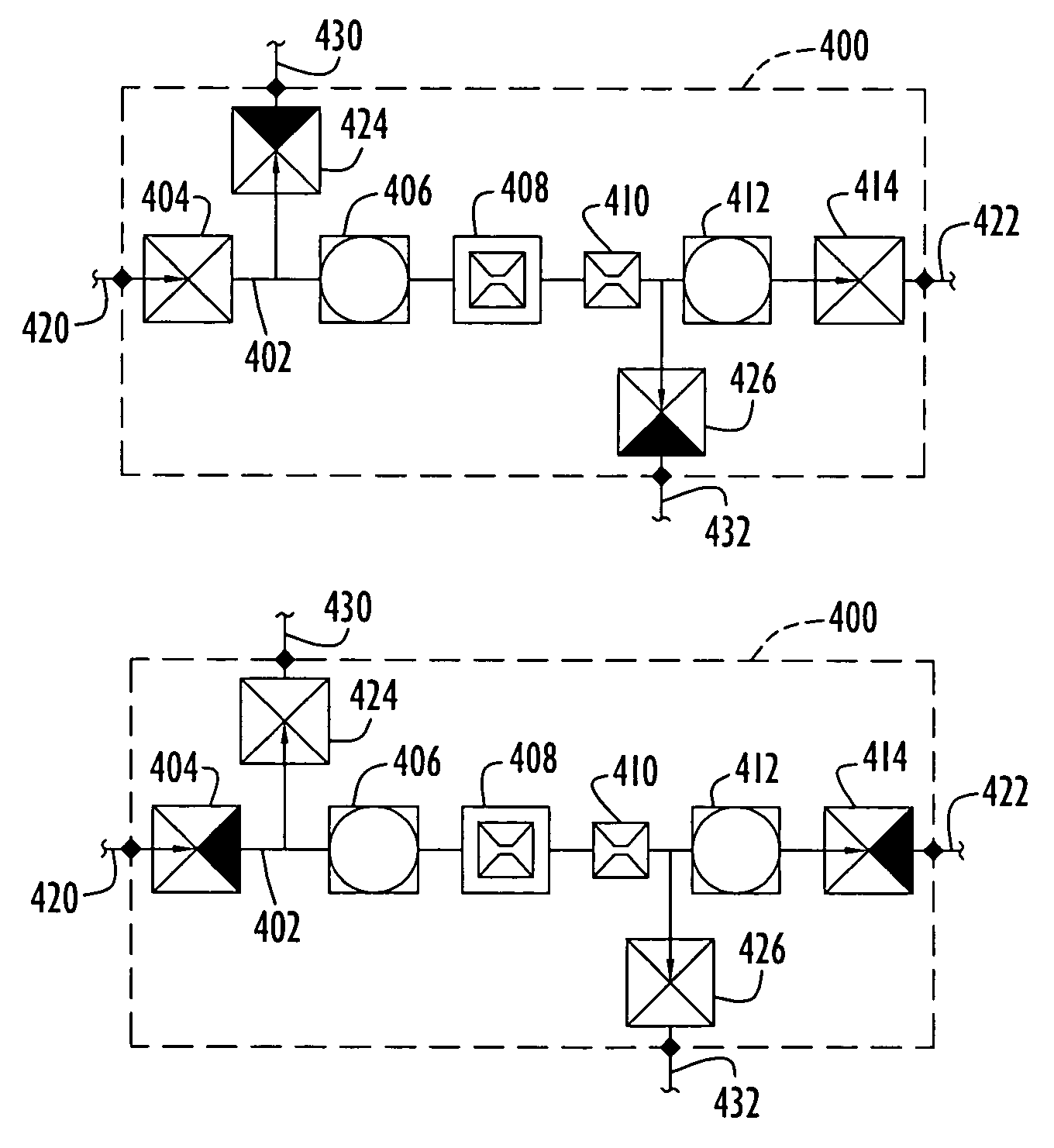
[0035]High purity fluid micro electromechanical systems (MEMS) are described that are capable of delivering liquid and / or gas streams to a delivery site while maintaining a high level of purity of the streams. The MEMS include a variety of miniature fluid processing components, such as valves, sensors (e.g., pressure, temperature, flow, galvanic, acoustic, optic, etc.), orifices, pumps, mixers, reservoirs, etc., that are disposed on one or more dies or blocks. Each of the MEMS components can be any conventional, commercially available or other suitable type. Examples of manufacturers of commercially available MEMS components (e.g., valves, pressure / temperature sensors, mass flow controllers, etc.) are Redwood Microsystems, Inc. (Menlo Park, Calif.), Analog Devices Inc. (Norwood, Mass.), and IC Mechanics, Inc. (Pittsburgh, Pa.).

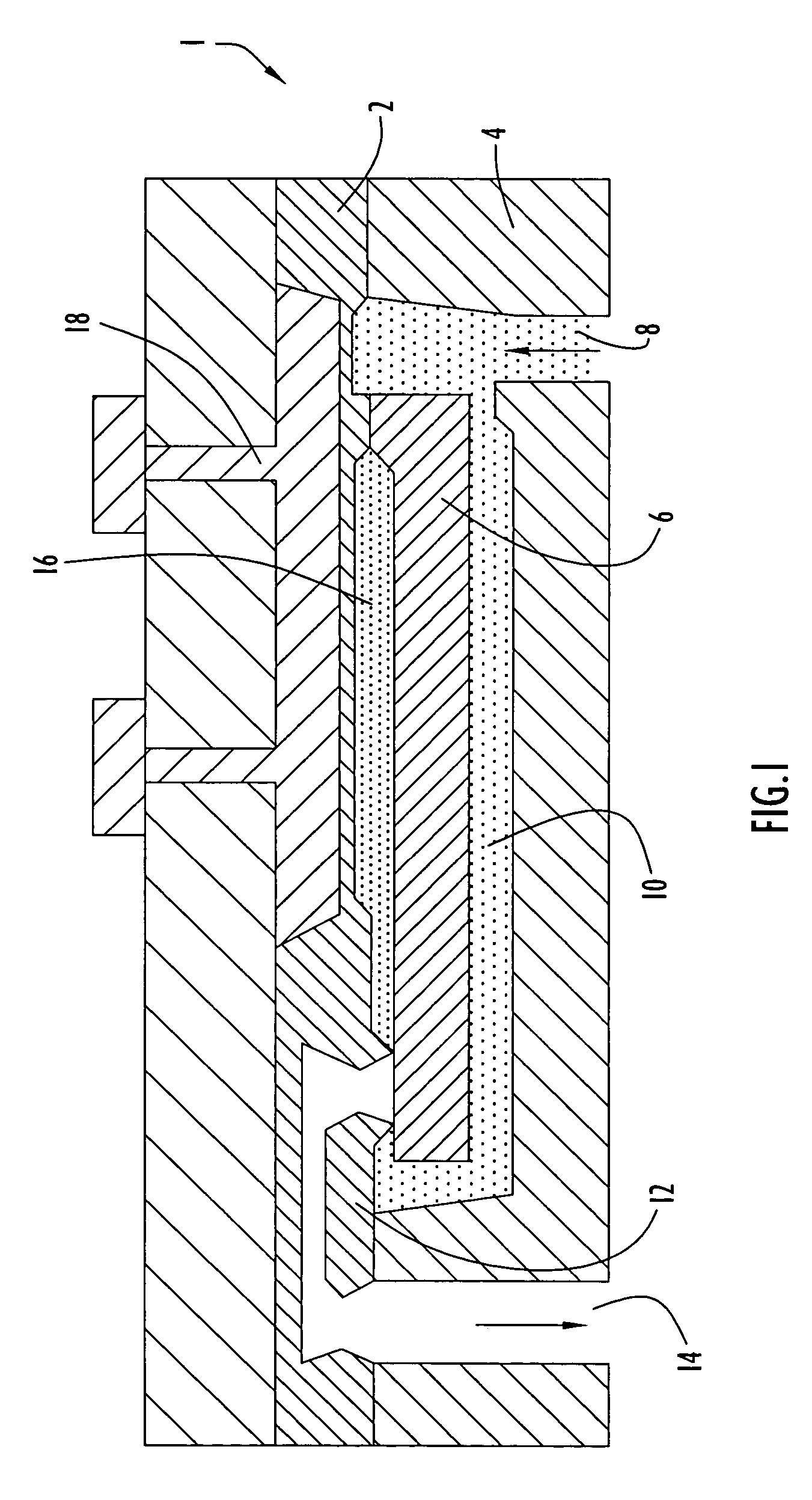
[0036]Typically, MEMS components are formed on one or more dies or blocks utilizing any one or a combination of MEMS manufacturing techniques including, witho...


PUM


Abstract

Complex fluidic micro electromechanical systems (MEMS) are incorporated into high purity chemical delivery systems, while maintaining valve sealing integrity, quality and performance of the system. In particular, fluidic MEMS systems are incorporated into high purity chemical delivery systems for semiconductor fabrication processes.

Description

CROSS REFERENCE TO RELATED APPLICATIONS[0001]This application claims priority from the following U.S. Provisional Patent Application Ser. Nos.: 60 / 436,731, entitled “Integrated Purge For MEMS-Based Liquid Mass Flow Controller and / or Meter”, filed Dec. 27, 2002; and 60 / 436,732, entitled “Reverse Orientation of Micro-Valves in Gas / Liquid Chemical Delivery Systems”, filed Dec. 27, 2002. The disclosures of these provisional patent applications are incorporated herein by reference in their entireties.BACKGROUND OF THE INVENTION[0002]1. Technical Field[0003]The present invention pertains to miniaturized chemical delivery systems. In particular, the present invention pertains to micro electromechanical systems for delivery of high purity chemicals to a manufacturing or other process.[0004]2. Discussion of the Related Art[0005]Micro electromechanical systems, or MEMS, are miniature systems used in a variety of applications. In particular, fluidic MEMS are used to transport and dispense gase...

Claims


Application Information

Patent Timeline
IPC IPC(8): F16K11/00B01J4/02B01J19/00B01L3/02
CPCB01J4/02B01J19/0093B01L3/0268B01L3/0265B01J2219/00891B01J2219/0099B01L2400/0638B01L2200/0689B01L2400/0487Y10T137/0419Y10T137/4259Y10T137/87877
Inventor ZNAMENSKY, DMITRYZDUNEK, ALAN
Owner AIR LIQUIDE AMERICA INC
Why Eureka
Eureka Blog
Learn More