Pneumatic syringe driver

a syringe driver and pneumatic technology, applied in the field of pneumatic syringe drivers, can solve the problems of large and complex syringe actuation devices, the size and power requirements of such devices suggest against their use, and the cost and complexity of such automatic devices

Active Publication Date: 2007-03-27
CARDINAL HEALTH SWITZERLAND 317 S A R L
View PDF2 Cites 49 Cited by
  • Summary
  • Abstract
  • Description
  • Claims
  • Application Information

AI Technical Summary

Benefits of technology

[0006]The presently disclosed invention pertains to a pneumatic syringe driver having a control module for regulating pressure applied to the piston of an associated syringe. The syringe driver is also adapted for receiving a canister of compressed gas such as carbon dioxide. A valve mechanism and conduits are provided in the driver for enabling the se

Problems solved by technology

While devices have been developed for automatic control over syringe actuation, the size and power requirements of such devices suggest against their use in environments in which space is limited or external power is not readily available.
However, in surgical settings, there tends to be minimal free space immediately proximate the surgical site, thus rendering large and complex syringe actuation devices inappropriate.
Furthermore, the cost

Method used


Image

  • Pneumatic syringe driver
  • Pneumatic syringe driver
  • Pneumatic syringe driver

Examples


Embodiment Construction

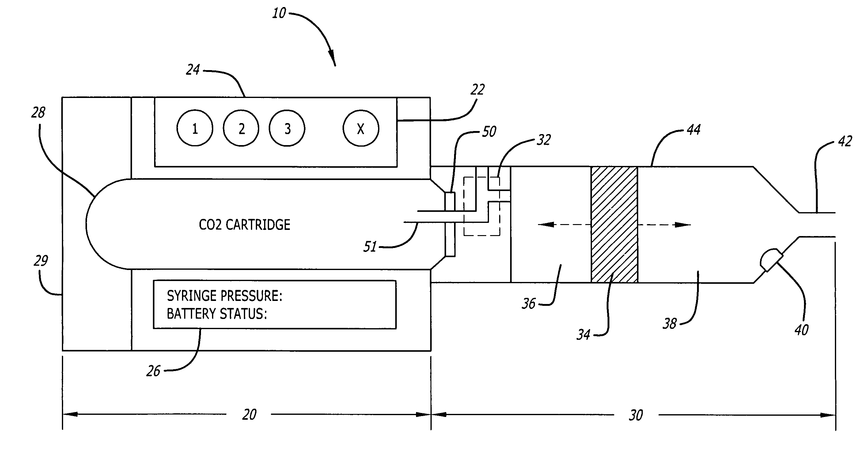
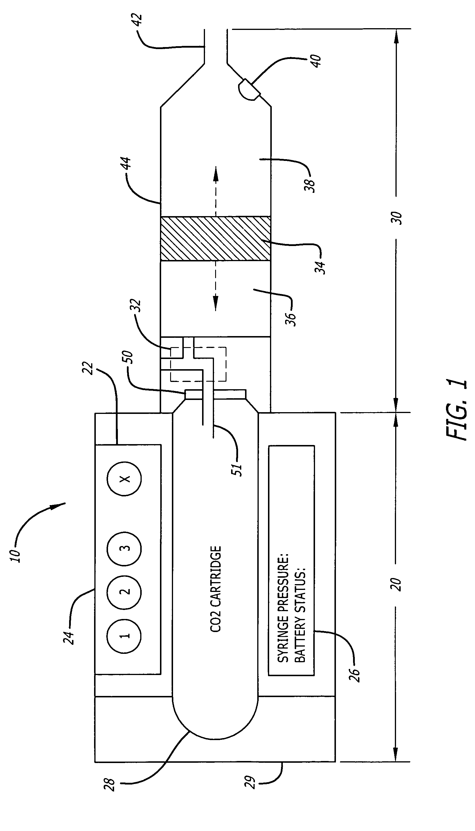
[0013]A first embodiment of the presently disclosed pneumatic syringe driver 10 is illustrated in FIG. 1. The device is comprised of two main portions, a control and gas canister portion 20 and a valve and syringe portion 30.

[0014]The control and gas canister portion 20 includes a control module 22, an operator input interface 24, an operator output interface 26, a battery compartment (not shown), and a gas canister receptacle 28.

[0015]The control module 22 may comprise a custom integrated circuit or a digital signal processor or micro-controller with an associated and custom-programmed memory. In communication with the control module 22 and three-way valve 32 is a battery (not shown). A variety of batteries may be employed depending upon the power requirements of the active elements of the driver 10. A small form factor is beneficial, however, due to the need for overall compactness. In an alternative embodiment, a power port is provided on the driver 10 for interfacing a remote po...


PUM


Abstract

A pneumatic syringe driver having a control module for regulating pressure applied to the plunger of an associated syringe is disclosed. The syringe driver is adapted for receiving a compressed gas canister and for enabling the selective release of gas from the canister into a chamber, one wall of which being formed by the syringe plunger via a three-way valve. The valve also enables the selective venting of gas from the canister into the atmosphere, thereby forming a venturi which reduces the pressure in the chamber and causes the syringe plunger to be withdrawn into the chamber. A pressure sensor in communication with the control module is provided for pressure feedback. Pushbuttons or switches in communication with the control module are provided for defining the syringe driver operation. The device is suited for the selective inflation and deflation of a balloon attached to the syringe driver for a balloon angioplasty procedures.

Description

CROSS REFERENCE TO RELATED APPLICATIONS[0001]This patent applications claims priority of U.S. Provisional Patent Application No. 60 / 322,832, filed Sep. 17, 2001.STATEMENT REGARDING FEDERALLY SPONSORED RESEARCH OR DEVELOPMENT[0002]N / ABACKGROUND OF THE INVENTION[0003]While devices have been developed for automatic control over syringe actuation, the size and power requirements of such devices suggest against their use in environments in which space is limited or external power is not readily available. Such devices have been employed for balloon inflation in various surgical procedures including the opening of strictures, or narrowings of bodily passages, such as in endoscopic dilation where a balloon is used to open an esophageal stricture. Another application is in balloon angioplasty. For example, such applications involve the use of a syringe for delivering pressurized fluid for inflating a balloon. However, in surgical settings, there tends to be minimal free space immediately pr...

Claims


Application Information

Patent Timeline
IPC IPC(8): A61M29/00A61M5/30
CPCA61M25/1018A61M5/14526A61M5/16881A61M25/10184A61M25/10185A61M25/10182A61M25/104
Inventor FLACHBART, ERIC J.
Owner CARDINAL HEALTH SWITZERLAND 317 S A R L
Why Eureka
Try Eureka