High throughput high-yield vacuum deposition system

a vacuum deposition and high-yield technology, applied in liquid/solution decomposition chemical coatings, instruments, solid-state diffusion coatings, etc., can solve the problems of insufficient thickness control for multi-layer coatings designed for dwdm and insufficient performan

Inactive Publication Date: 2007-03-27
TERAPHYSICS CORP
View PDF8 Cites 25 Cited by
  • Summary
  • Abstract
  • Description
  • Claims
  • Application Information

AI Technical Summary

Benefits of technology

[0015]A vacuum deposition system has been designed that in one embodiment may be used for production of narrow band pass filters for use in mux and demux devices of DWDM systems. The filter production system may utilize a high-yield fixture assembly such as the Vornado™ and a novel moving electron gun assembly which in one embodiment a

Problems solved by technology

This level of thickness control is insufficient for multilayered coatings designed for DWDM.
Customers for the filt

Method used


Image

  • High throughput high-yield vacuum deposition system
  • High throughput high-yield vacuum deposition system
  • High throughput high-yield vacuum deposition system

Examples


Embodiment Construction

[0032]Referring now to the drawings, which are for purposes of illustrating at least one embodiment of the invention only, and not for purposes of limiting the invention, FIGS. 2A and 2B show the invention as described with reference to at least one embodiment.

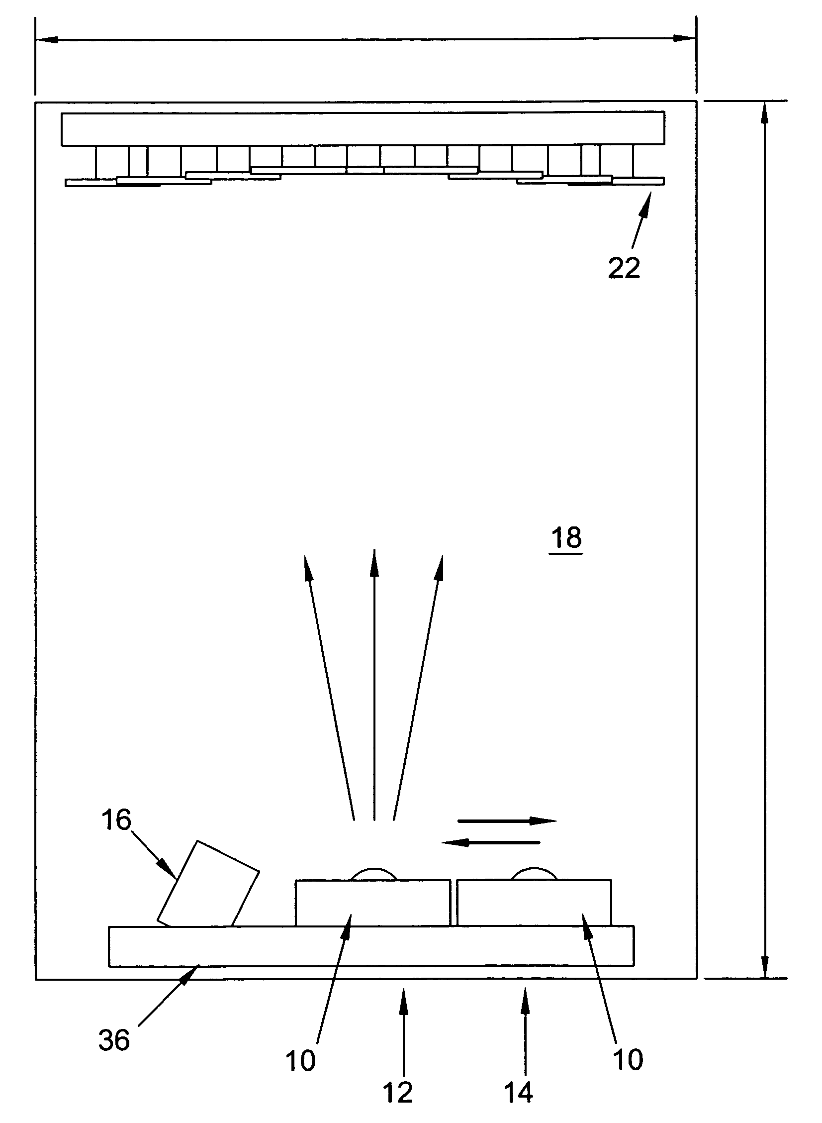
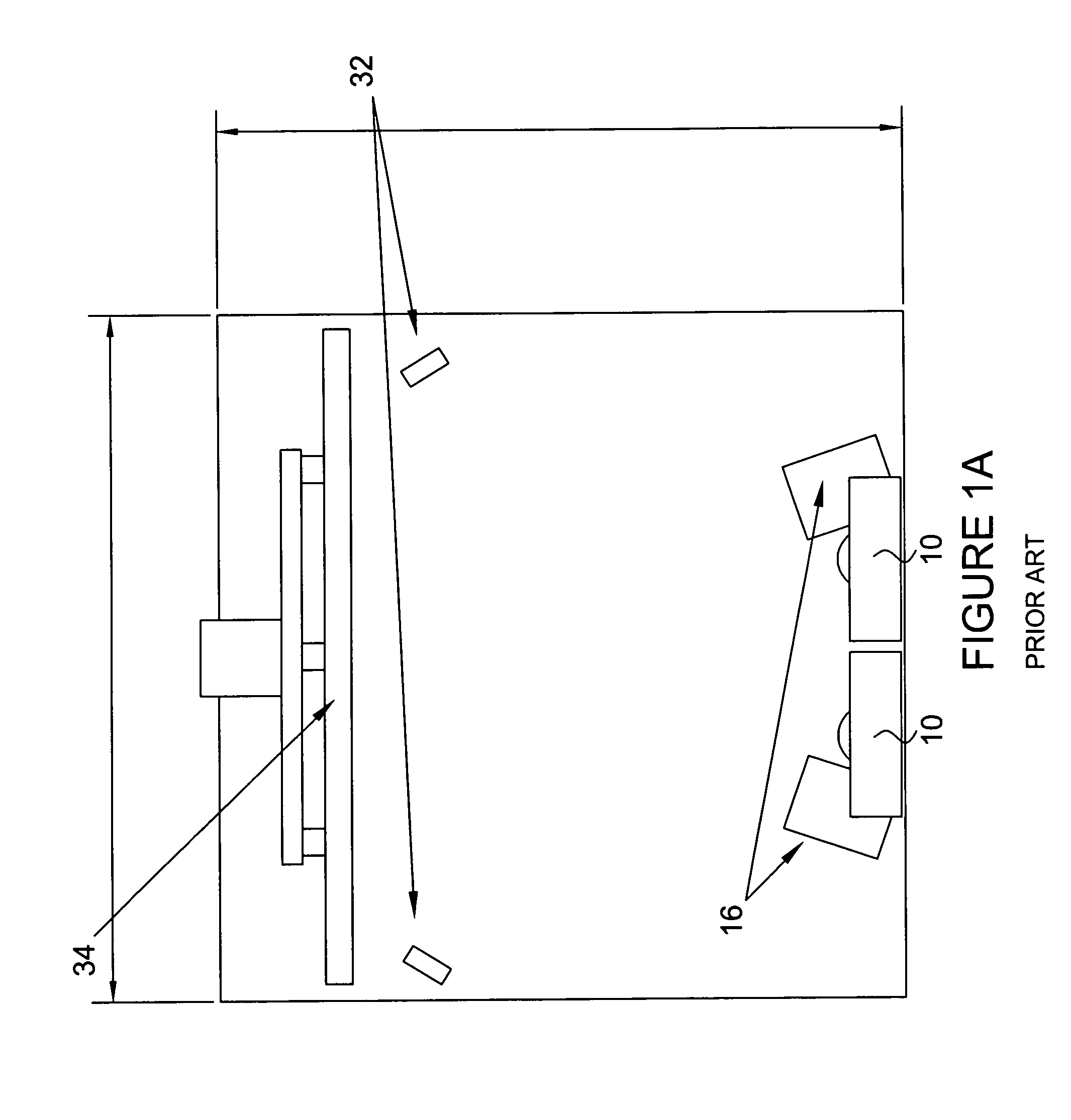
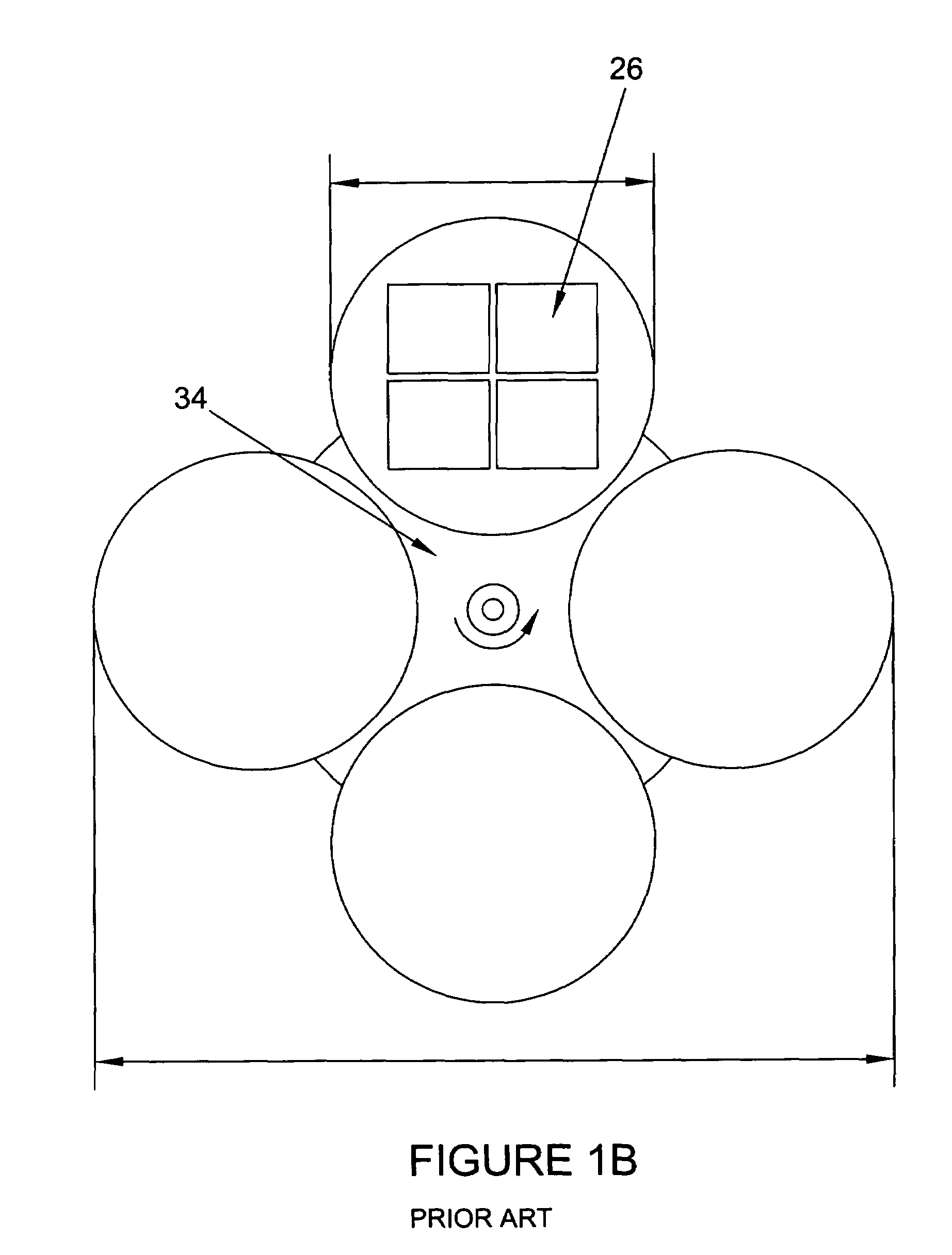
[0033]FIGS. 2A and 2B show one embodiment of the inventive assembly, including evaporators 10, a source deposition location 12, a standby position 14, a fixed ion source 16, a vacuum chamber 18, fixed array 20, fixtures 22, substrate 26, disk 28, rotation mechanism 30, and QCM 32. The fixtures 22 are located in a dense high yield array 20, as shown in FIGS. 2A and 2B. The fixtures 22 are in close proximity to each other, in order to utilize as many substrates 26 as possible.

[0034]In one embodiment, an ion assisted electron beam evaporation system has been configured to produce narrow band pass filters for DWDM multiplexers with high throughput and maximum yield. The system significantly improves uniformity of coated substrates...


PUM

PropertyMeasurementUnit
Fractionaaaaaaaaaa
Fractionaaaaaaaaaa
Fractionaaaaaaaaaa

Abstract

A vacuum deposition system has been designed to produce thin film based demultiplexers with high throughput and production yields of greater than 25% for use in Dense Wavelength Division Multiplexer (DWDM) systems. The system employs a dense array of high yield fixtures and an ion assisted movable dual electron beam evaporation system. The fixture array increases acceptable yields of narrow band pass filters to 25–75% compared to less than 5% in conventional coating systems used for DWDM. The movable e-beam system allows critical symmetry to be maintained while eliminating significant delays resulting from deposition of two materials from a single electron gun. The vacuum deposition system will enable production of more than 15,000 50–200 GHZ filters which meet specifications for DWDM demultiplexers every 48 hours.

Description

[0001]This application claims priority to U.S. Provisional patent application Ser. No. 60 / 217,060, entitled HIGH THROUGHPUT HIGH-YIELD VACUUM DEPOSITION SYSTEM FOR THIN FILM BASED DENSE WAVELENGTH DIVISION MULTIPLEXERS, filed on Jul. 10, 2000 and U.S. Provisional patent application Ser. No. 60 / 217,115, entitled SUBSTRATE FIXTURE FOR HIGH-YIELD PRODUCTION OF THIN FILM BASED DENSE WAVELENGTH DIVISION MULTIPLEXERS, filed on Jul. 10, 2000.I. BACKGROUND OF THE INVENTION[0002]A. Field of the Invention[0003]In at least one aspect, the present invention relates to film deposition useful in the installation of a worldwide fiber-optic network, which is in progress, capable of handling levels of data transmission inconceivable only several years ago. As a result of this network, the Internet is less than half a decade away from being a more useful tool than the computers which navigate it. Advanced thin film coatings have emerged as the enabling technology to control transmission and reflectio...

Claims


Application Information

Patent Timeline
IPC IPC(8): C23C16/00C23C14/22C23C14/50C23C14/54G02B6/34
CPCB82Y10/00C23C14/22C23C14/546C23C14/505G02B6/29361
Inventor MEARINI, GERALD T.TAKACS, LASZLO
Owner TERAPHYSICS CORP
Why Eureka
Try Eureka