Laser measuring method and laser measuring system having fan-shaped tilted laser beams and three known points of photodetection system

a laser measuring system and laser measuring technology, applied in the direction of navigation instruments, instruments for comonautical navigation, instruments, etc., can solve the problems of inaccurate installation, difficult to perform, and difficult to carry out the measurement operation itself, so as to improve the working efficiency and eliminate errors

Active Publication Date: 2007-03-27
KK TOPCON
View PDF6 Cites 23 Cited by
  • Summary
  • Abstract
  • Description
  • Claims
  • Application Information

AI Technical Summary

Benefits of technology

[0008]It is an object of the present invention to provide a laser measuring system, in which a rotary laser system can be installed at any desired point and by which it is possible to perform accurate measurement without being influenced by installing conditions such as tilting of the rotary laser system, and deviation of the rotary laser system can be confirmed and corrected when positional deviation occurs at a later time after the installation.
[0011]According to the present invention, a laser measuring method is provided, which comprises a rotary laser system for projecting a laser beam by rotary irradiation and at least one photodetection system having at least one photodetector for receiving the laser beam, comprising a step of emitting at least two fan-shaped laser beams by the rotary laser system, at least one of the fan-shaped laser beams being tilted, a step of receiving the laser beams at least at three known points by the photodetection system, a step of obtaining elevation angles with respect to the rotary laser system based on photodetection signals which are formed when the photodetector receives the laser beam, and a step of measuring an installing position of the rotary laser system based on elevation angles and position data at the three known points. As a result, there is no need to install the rotary laser system at a known point. This contributes to the improvement of working efficiency and to the elimination of error, which may occur during installation. Also, when the position of the rotary laser system is deviated after installation, the installing position can be corrected.

Problems solved by technology

However, accurate installation requires skill and is difficult to perform.
Depending on the circumstances, there may be no adequate known point for installing the rotary laser system or there may be environmental condition not suitable for installing the rotary laser system at a known point.
In such cases, there has been such problem that measuring operation itself is often difficult to carry out.
When the rotary laser system can be installed, there is no effective method to verify whether the rotary laser system has been accurately installed or not.
Further, when the rotary laser system is installed in tilted condition, error may occur with respect to the known point but there has been no effective method to detect such error.
Also, when deviation of position occurs due to later cause after the system has been installed, there has been no effective method to detect such deviation.

Method used


Image

  • Laser measuring method and laser measuring system having fan-shaped tilted laser beams and three known points of photodetection system
  • Laser measuring method and laser measuring system having fan-shaped tilted laser beams and three known points of photodetection system
  • Laser measuring method and laser measuring system having fan-shaped tilted laser beams and three known points of photodetection system

Examples


Embodiment Construction

[0026]Description will be given below on the best aspect to carry out the present invention referring to the drawings.

[0027]First, description will be given on general features of a rotary laser system and a photodetection system used in the present embodiment referring to FIG. 1 to FIG. 3.

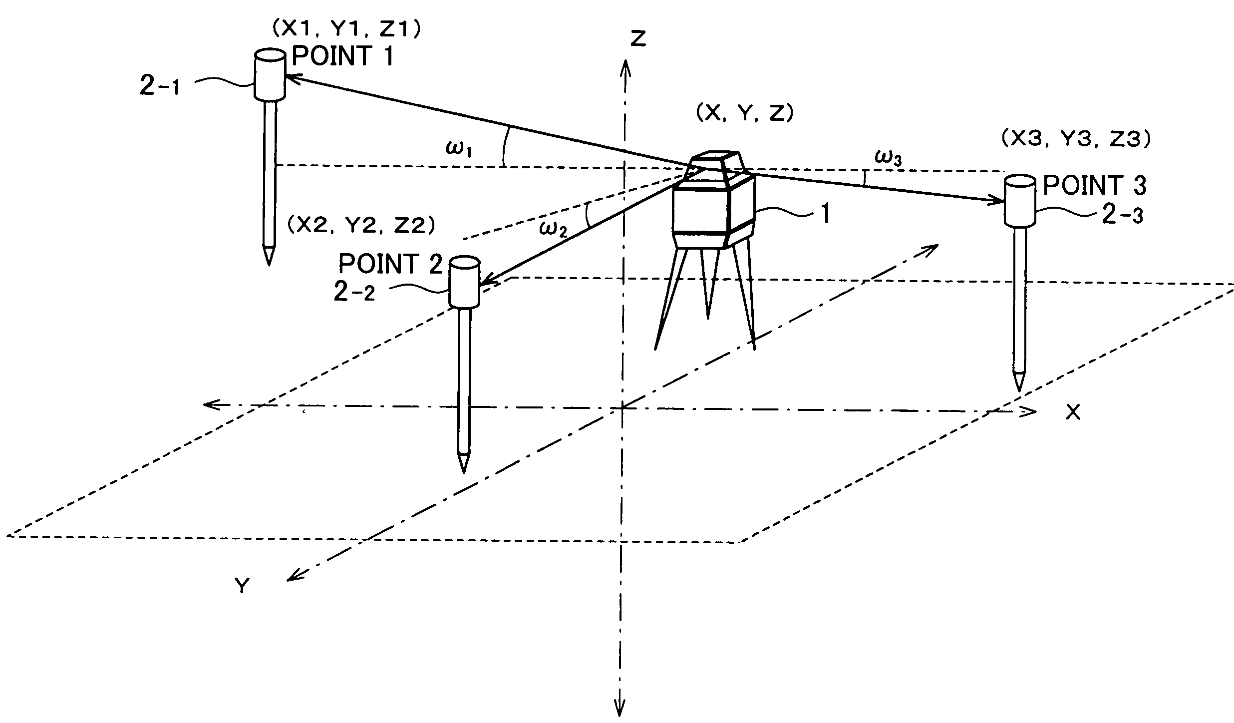
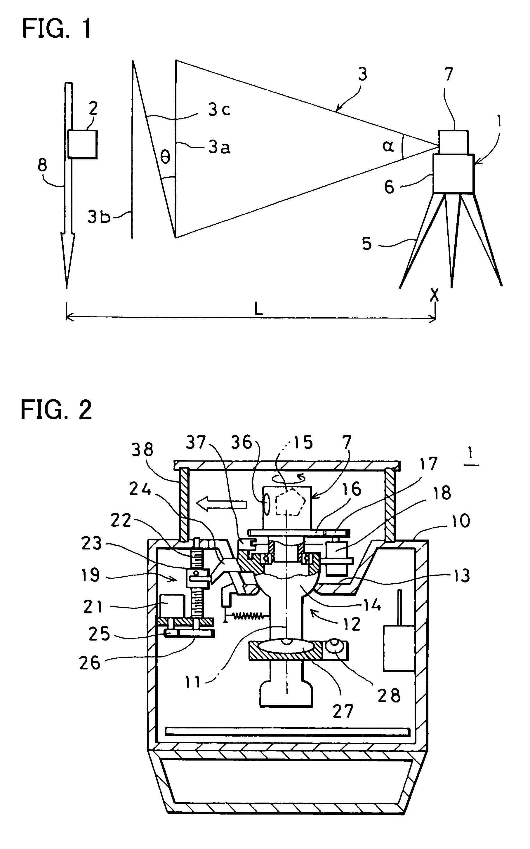
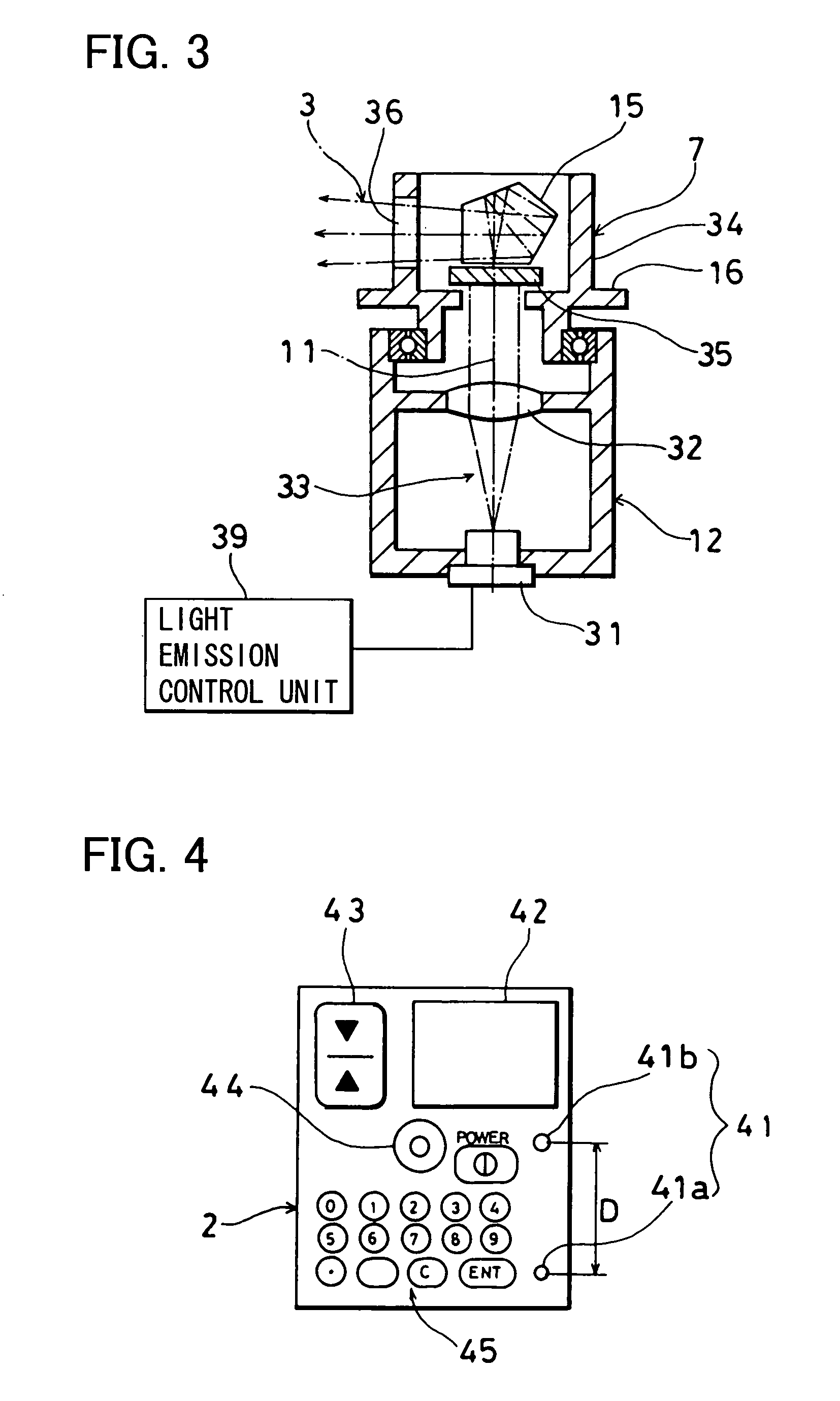
[0028]A rotary laser system 1 projects a plurality of fan-shaped laser beams by rotary irradiation. A photodetection system 2 comprises a photodetection unit 41 (to be described later). The photodetection unit 41 comprises at least one photodetector (in the figure, two photodetectors are shown), which receives the fan-shaped laser beams.

[0029]A tripod 5 is installed at a position to approximately align with an approximately known point X, and the rotary laser system 1 is mounted on the tripod 5. The rotary laser system 1 comprises a main unit 6 and a rotating unit 7 rotatably mounted on the main unit 6. A laser beam 3 is projected by rotary irradiation from the rotating unit 7. The photodetection ...


PUM


Abstract

A laser measuring method in a laser measuring system, which comprises a rotary laser system for projecting a laser beam by rotary irradiation and at least one photodetection system having at least one photodetector for receiving the laser beam, comprising a step of emitting at least two fan-shaped laser beams by the rotary laser system, at least one of the fan-shaped laser beams being tilted, a step of receiving the laser beams at least at three known points by the photodetection system, a step of obtaining elevation angles with respect to the rotary laser system based on photodetection signals which are formed when the photodetector receives the laser beam, and a step of measuring an installing position of the rotary laser system based on elevation angles and position data at the three known points.

Description

BACKGROUND OF THE INVENTION[0001]The present invention relates to a laser measuring method and a laser measuring system, by which a laser beam is projected by rotary irradiation for the purpose of forming a horizontal reference plane or a reference plane tilted with respect to the horizontal reference plane at a predetermined angle and by which it is possible to measure a position by receiving the laser beam.[0002]As a representative system for forming a reference plane by projecting a laser beam by rotary irradiation, a rotary laser system installed at a known point and a photodetection system installed at a measuring point and used for receiving a laser beam from the rotary laser system have been known in the past.[0003]A rotary laser system forms a reference plane by projecting a laser beam with a cross-section of luminous flux in spot-like shape. For instance, when the laser beam is projected in a horizontal plane by rotary irradiation, a horizontal reference plane is formed. Wh...

Claims


Application Information

Patent Timeline
Patent Type & Authority Patents(United States)
IPC IPC(8): G01C21/02G01C15/00G01C15/06
CPCG01C15/002G01C15/004
Inventor OHTOMO, FUMIOOSARAGI, KAZUKIHAYASHI, KUNIHIRODAVIDSON, RICHARD W.GOAD, CLYDE C.BRABEC, VERNON J.FALCON, EDUARDO F.JACKSON, RICHARD J.
Owner KK TOPCON
Why Eureka
Try Eureka