Wide scanning x-ray source

a wide scanning and source technology, applied in the field of x-ray imaging systems, can solve the problems of reducing image quality, limiting the scanning width of objects, and reducing the use of single focal spot tubes with larger detector arrays, so as to reduce the exposure of x-ray to patients, increase scanning speed, and wide scan

Active Publication Date: 2007-03-27
GE MEDICAL SYST GLOBAL TECH CO LLC
View PDF14 Cites 42 Cited by
  • Summary
  • Abstract
  • Description
  • Claims
  • Application Information

AI Technical Summary

Benefits of technology

[0012]The embodiments of the present invention provide several advantages. One such advantage is the provision of an imaging tube having an adjustable cathode and an anode having multiple target surfaces, together providing a relatively wide scan as compared to traditional imaging tubes. The electron beam of the cathode may be steered and the focal spot of that electron beam may be altered in response to electrical potentials within the electron beam “gun” or cathode. In providing a wide scan, the present invention is capable of scanning a full organ in a single rotation of a gantry, thereby, increasing scanning speed and minimizing x-ray exposure to a patient.
[0013]Another advantage provided by an embodiment of the present invention is the provision of a cathode that is a member of a replaceable subassembly, which allows the cathode to be easily maintained and replaced.
[0014]Furthermore, another advantage provided by an embodiment of the present invention is the efficient x-ray production by incorporating forward angle x-ray generation for incident angles less than 90°, which allows for greater x-ray radiation output per unit of heat or power input into a target surface. This increases efficiency of an imaging tube.
[0015]Moreover, another advantage provided by an embodiment of the present invention is the provision of an x-ray window that has a length that corresponds with a width associated with multiple adjacently emitted x-ray beams and as such minimizes x-ray absorption or thermal absorption by the x-ray window, thus minimizing the temperature of the window so that the window does not experience thermal or heat-related mechanical stresses, cracks, fractures, or other undesirable characteristics.

Problems solved by technology

Traditionally, scanning widths of an object have been limited due to the feasibly usable maximum angle of the x-ray beam and capabilities of the detector array, which in combination affect quality of a reconstructed image.
A fundamental limit exists when using a single focal spot tube with larger width detector arrays.
The larger the width of the detector arrays the more cone-beam artifacts that are produced, causing a reduction in image quality.
Another limit associated with single focal spot tubes is that the resolving power of the electron beam decreases from a center ray, extending through the center of the focal spot, towards outer edges of the focal spot.
Therefore, detector elements farther away from a center of the focal spot receive a lower resolving power causing poorer image quality for the elements with lower resolving power.
CT imaging systems are limited in scanning speed of an image due to the maximum angle of the x-ray beam.
With the current scanning angle, for example, only a portion of an organ can be scanned for a single revolution of the gantry, thus requiring multiple rotations and significant amounts of scanning time.
Spit activity can reduce image quality and potentially prevent image reconstruction.

Method used


Image

  • Wide scanning x-ray source
  • Wide scanning x-ray source
  • Wide scanning x-ray source

Examples


Embodiment Construction

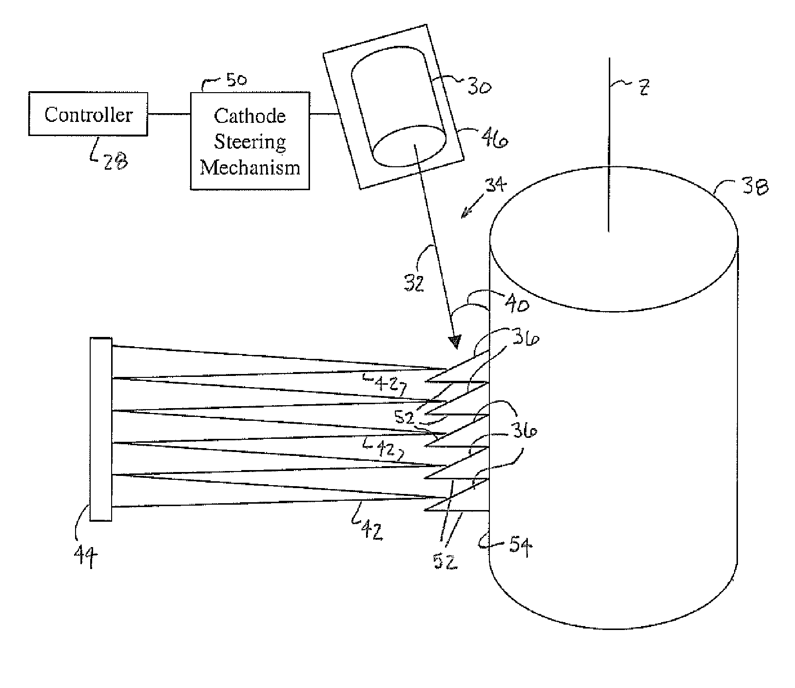
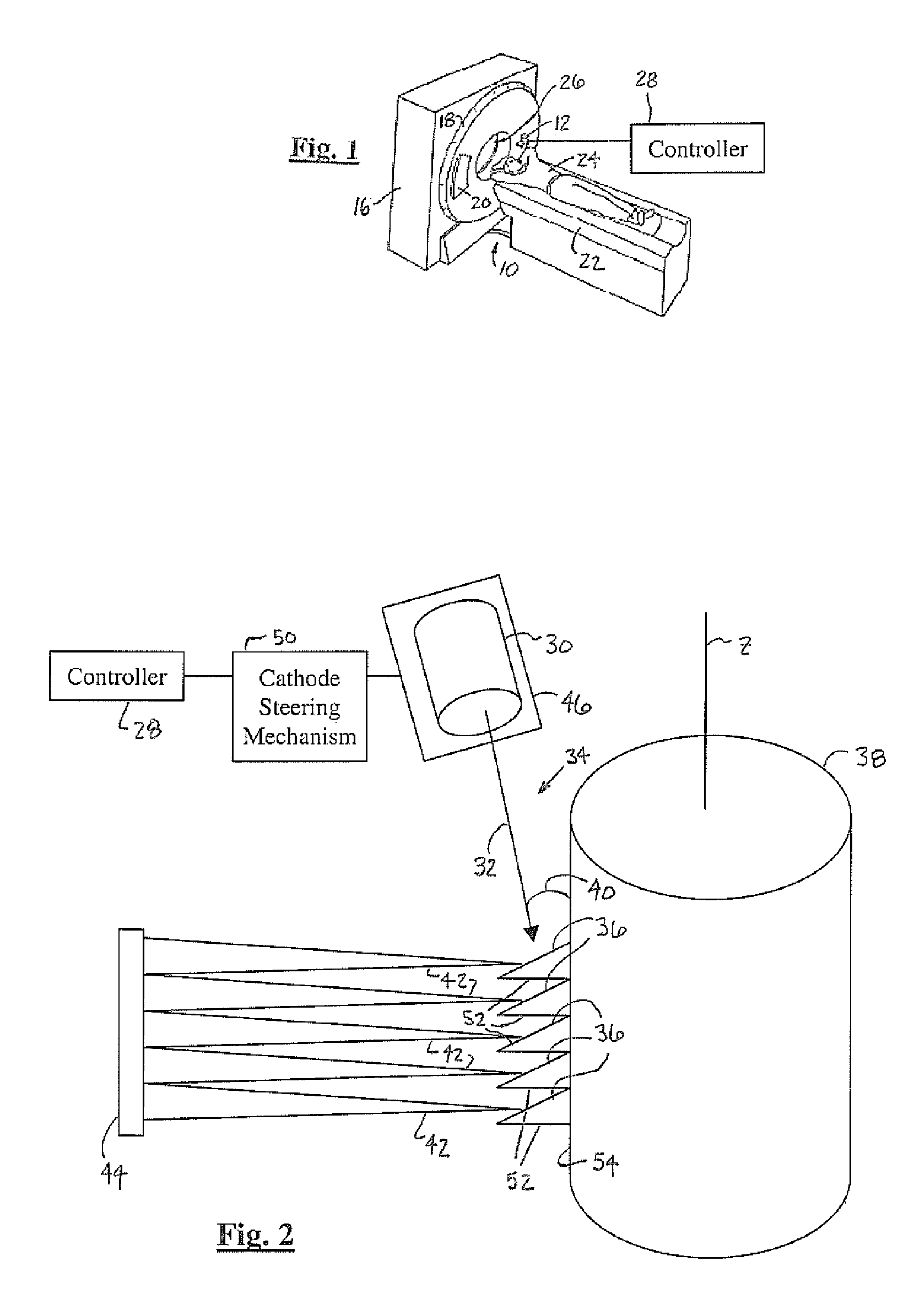
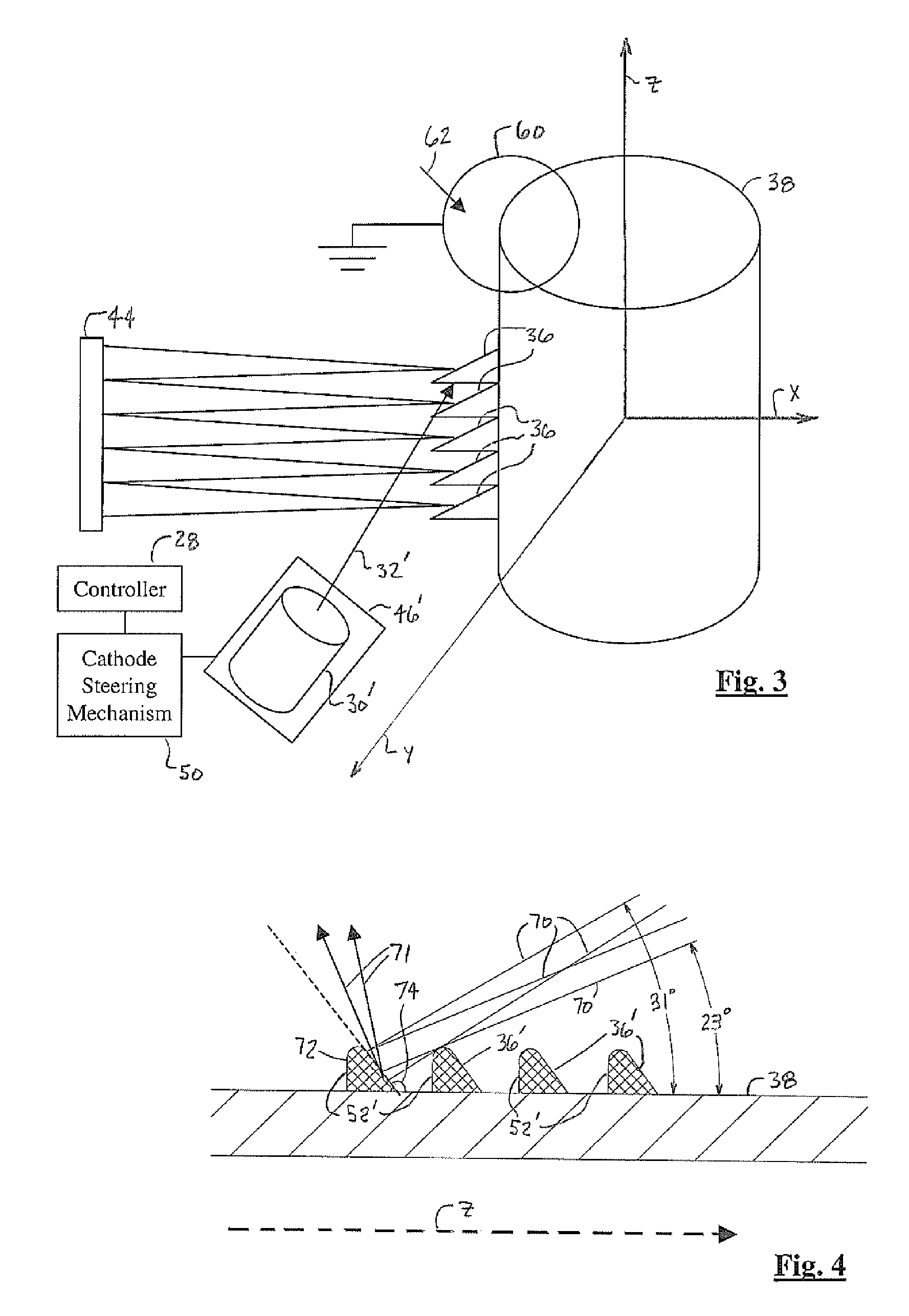
[0026]In each of the following figures, the same reference numerals are used to refer to the same components. While the present invention is described with respect to a method and system for performing a wide scan of an object within an computed tomography (CT) imaging system, the following apparatus and method is capable of being adapted for various purposes and is not limited to the following applications: CT systems, radiotherapy systems, x-ray imaging systems, ultrasound systems, nuclear imaging systems, magnetic resonance spectroscopy systems, and other applications known in the art.

[0027]Also, the present invention although described as being used in conjunction with a CT tube may be used in conjunction with other imaging tubes including x-ray tubes and vascular tubes.

[0028]Additionally, the terms “wide scan” refer to an x-ray source scanning width that is approximately greater than 10 mm. For example, in one embodiment of the present invention an x-ray source of the present i...


PUM


Abstract

An imaging tube (12) includes a cathode (30) that emits an electron beam (32) and an anode (38). The anode (38) includes multiple target surfaces (36). Each of the target surfaces (36) has a focal spot that receives the electron beam (32). The target surfaces (36) generate multiple x-ray beams (42) in response to the electron beam (32). Each x-ray beam (42) is associated with one of the target surfaces (36). An x-ray imaging system (10) includes the cathode (30) and the anode (38). A controller (28) is electrically coupled to the cathode (30) and adjusts emission of the electron beam (32) on the anode (38).

Description

TECHNICAL FIELD[0001]The present invention relates generally to x-ray imaging systems, and more particularly, to a system and method of performing a wide scan of an object within an x-ray imaging system.BACKGROUND OF THE INVENTION[0002]Traditional x-ray imaging systems include an x-ray source and a detector array. X-rays are generated by the x-ray source, passed through an object, and are detected by the detector array. Electrical signals generated by the detector array are conditioned to reconstruct an x-ray image of the object.[0003]CT imaging systems include a gantry that rotates at various speeds in order to create a 360° image. The gantry contains an x-ray source having a single focal spot CT tube assembly that generates x-rays across a vacuum gap between a cathode and an anode. In order to generate the x-rays, a large voltage potential is created across the vacuum gap allowing electrons, in the form of an electron beam, to be emitted from the cathode to a single target surface...

Claims


Application Information

Patent Timeline
Patent Type & Authority Patents(United States)
IPC IPC(8): H01J35/08
CPCH01J35/10H01J35/30H01J35/14H01J2235/086H01J35/153
Inventor DUNHAM, BRUCE M.PRICE, JOHN SCOTT
Owner GE MEDICAL SYST GLOBAL TECH CO LLC
Why Eureka
Try Eureka