Disk drive with AC exciter for head/disk interface

Inactive Publication Date: 2007-04-03
MAXTOR
View PDF29 Cites 48 Cited by
  • Summary
  • Abstract
  • Description
  • Claims
  • Application Information

AI Technical Summary

Benefits of technology

[0037]In yet another embodiment, the present invention may be configured as a flying height control system or method. The application of the AC exciter signal across the head/disk interface creates an attraction force between the head and the disk. Altering the AC exciter signal increases or decreases the head/disk attraction force and causes the head to move towards the disk against the cumulative preload forces that bias the head away from the disk. Accordingly, the AC exciter can be used as part of a feedback system for controlling the flying height of the head. The reaction time of the feedb

Problems solved by technology

However, the DC voltage applied to the head/disk interface can polarize the head/disk interface.
Polarization of the head/disk interface can alter the characteristics of the read and write system

Method used


Image

  • Disk drive with AC exciter for head/disk interface
  • Disk drive with AC exciter for head/disk interface
  • Disk drive with AC exciter for head/disk interface

Examples


Embodiment Construction

[0054]The present invention may be embodied in a number of different configurations depending upon the requirements of the disk drive in which it is implemented. A number of different examples of each of these configurations will be discussed below.

I. ELECTROSTATIC DISCHARGE SYSTEMS

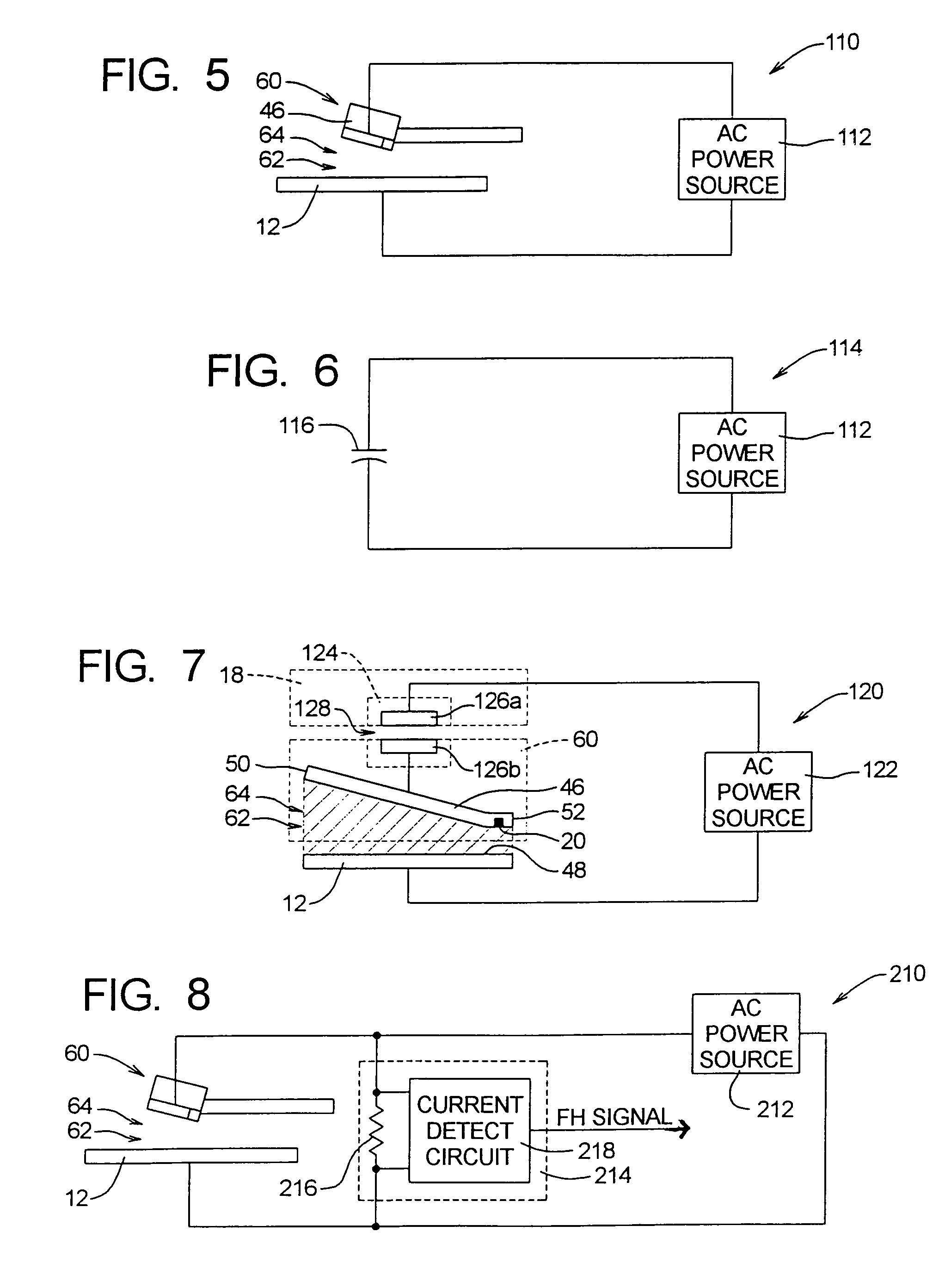
[0055]FIG. 5 illustrates a block diagram of first exemplary electrostatic discharge system 110 constructed in accordance with and embodying the principles of the present invention. The electrostatic discharge system 110 comprises an AC power source 112, and the head 60 and the disk 12 of a conventional disk drive 10.

[0056]The AC power source 112 generates an AC exciter signal and is operatively connected to the head 60 and the disk 12. More specifically, the AC power source 112 is connected to the disk 12 and to the slider 46 of the head 60 such that an AC electric potential is created across the flying height gap 64 at the head / disk interface 62. By creating an alternating current electric potential acro...


PUM


Abstract

A disk drive includes a disk for storing information, a head with a transducer that writes data to and reads data from the disk, and an AC power source. The head is suspended adjacent to the disk and a flying height gap exists at the head/disk interface. The AC power source generates an AC exciter signal across the flying height gap that discharges electrostatic charge at the head/disk interface. The head/disk capacitance can be measured based on the AC exciter signal to sense the flying height. The AC exciter signal can also alter an attraction force between the head and the disk and thus control flying height. The AC exciter signal can also be based on a flying height signal representative of the head/disk capacitance and thus the flying height.

Description

RELATED APPLICATIONS[0001]Priority is claimed from U.S. Provisional Patent Application Ser. No. 60 / 339,458 filed on Dec. 11, 2001, which is incorporated by reference in its entirety.FIELD OF THE INVENTION[0002]The present invention relates to digital storage devices and, more particularly, to hard disk drives.BACKGROUND OF THE INVENTION[0003]A disk drive is a digital data storage device that stores information within concentric tracks on a storage disk. The disk is coated on both of its primary surfaces with a magnetic material that is capable of changing its magnetic orientation in response to an applied magnetic field. During operation of the disk drive, the disk is rotated about a central axis at a constant rate. To read data from or write data to the disk, a magnetic transducer (or head) is positioned above (or below) a desired track of the disk while the disk is spinning.[0004]Writing is performed by delivering a polarity-switching write current signal to the transducer while t...

Claims


Application Information

Patent Timeline
IPC IPC(8): G11B21/02
CPCG11B5/6017G11B21/21
Inventor SCHRECK, ERHARD T.EATON, ROBERT E.
Owner MAXTOR
Why Eureka
Try Eureka