Drive control apparatus and drive control method for optical modulator

a technology of optical modulator and control apparatus, which is applied in the direction of electrical apparatus, electromagnetic receivers, instruments, etc., can solve the problems of difficult to determine the frequency of the superimposed component, the fluctuation amount and the fluctuation direction of the operating point of the mz optical modulator on the clock modulation side, and the code interfering in the on/off level of the optical output, etc., to achieve reliably compensate for the change of operating point and simple configuration

Inactive Publication Date: 2007-04-03
FUJITSU LTD
View PDF65 Cites 47 Cited by
  • Summary
  • Abstract
  • Description
  • Claims
  • Application Information

AI Technical Summary

Benefits of technology

[0015]The present invention has been accomplished in view of the abovementioned problems with the object of providing a drive control apparatus and a drive control method with a simple configuration, which can also reliably compensate for operating point changes of an optical modulator driven in accordance with a drive signal corresponding to a clock signal.

Problems solved by technology

However, there is a problem in that the optical output characteristics with respect to the drive signal drift timewise due to temperature change and a change with time, resulting in that interference between the codes occurs in the on / off level of the optical output.
Consequently, in the conventional method of superimposing the operating point control signal, it is difficult to detect the fluctuation amount and the fluctuation direction of the operating point in the MZ optical modulator on the clock modulation side.
Also, in the method which controls the operating point by detecting that the frequency of the superimposed component contained in the output from the optical modulator becomes twice the frequency of the operating point control signal, in the MZ light modulator-on the clock modulation side, since the point where the optical output becomes a maximum is only temporary as described above, the detection signal becomes faint so that it is difficult to determine the frequency of the superimposed component.
Moreover, in the conventional method, there is also a problem in that when the amplitude of the drive signal is shifted from 2Vπ, then in the optical output, two bias points exist which generate a superimposed component with twice the frequency of the operating point control signal, and in the case where the operating point is controlled based on either of the bias points as a reference, only output waveforms with deviated duty are obtained, so that normal modulation operation cannot be realized.
Therefore, there is a disadvantage in that when providing the additional configurations for the conventional drive control, this invites a higher cost and a larger size for the transmission section.

Method used


Image

  • Drive control apparatus and drive control method for optical modulator
  • Drive control apparatus and drive control method for optical modulator
  • Drive control apparatus and drive control method for optical modulator

Examples


first embodiment

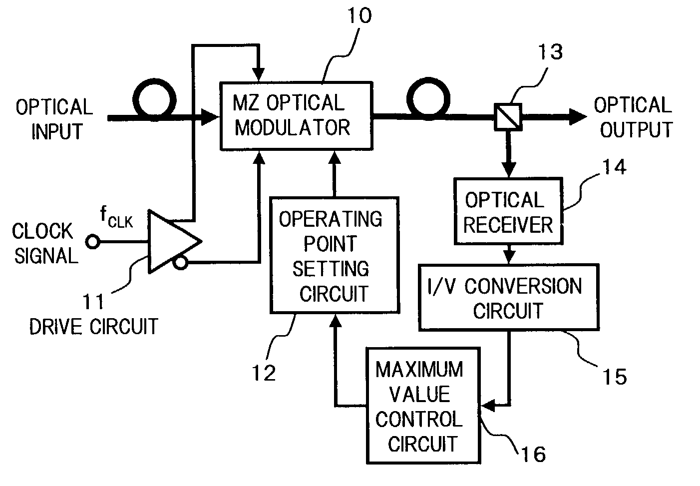
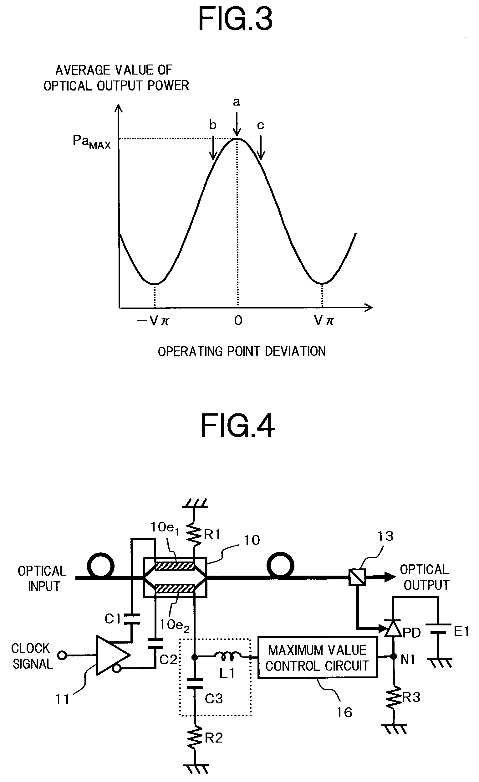
[0072]FIG. 4. is a circuit diagram showing a configuration of the drive control apparatus according to a Components of the same configuration as that shown in FIG. 1 are denoted by the same reference numerals, and similarly for the other embodiments hereunder.

[0073]In the circuit configuration of FIG. 4, one drive signal generated by the drive circuit 11 that receives the clock signal is applied to one end of a signal electrode 10e1 (at the top in FIG. 4) of the MZ optical modulator 10 via a capacitor C1. Moreover, the other drive signal with a phase different of 180° from that of the one drive signal, is applied to one end of a signal electrode 10e2 (at the bottom in FIG. 4) of the MZ optical modulator 10 via a capacitor C2. Here, the other end of the signal electrode 10e1 of the MZ optical modulator 10 is terminated through a resistor R1. Moreover, the other end of the signal electrode 10e2 is terminated through a capacitor C3 in a BIAS-T circuit and a resistor R2.

[0074]Furthermo...

second embodiment

[0084]FIG. 8 is a functional block diagram showing the configuration of the drive control apparatus of the

[0085]In FIG. 8, the drive control apparatus for the MZ optical modulator according to the present embodiment is configured such that, for example, in a typical structure of the CS-RZ modulation method in which there is sequentially connected; an MZ optical modulator 20 on a data modulation side that is driven in accordance with a drive signal obtained by adjusting a data signal of bit rate fob / s corresponding to the NRZ modulation method by a drive circuit 21 so that the amplitude thereof becomes Vπ, and an MZ optical modulator 10 on a clock modulation side that is driven in accordance with a drive signal obtained by adjusting a clock signal having a frequency fCLK (=f0 / 2)Hz, that is ½ the bit rate of the above mentioned data signal by a drive circuit 11 so that the amplitude thereof becomes 2Vπ, the aforementioned basic structure shown in FIG. 1 is applied to the MZ optical mo...

third embodiment

[0093]Next is a description of the drive control apparatus of the MZ optical modulator having the above mentioned basic configuration shown in FIG. 1.

[0094]FIG. 9 is a functional block diagram showing the configuration of the drive control apparatus of the third embodiment.

[0095]In FIG. 9, the part where the configuration of this drive control apparatus differs from the basic configuration of FIG. 1 is that there is provided an amplitude adjusting circuit 17 adjusting the amplitude of the drive signal corresponding to the clock signal. The, configuration of other parts is the same as for the basic configuration of FIG. 1.

[0096]Here, at first, the optical output characteristics when the amplitude of the drive signal to be applied to the MZ optical modulator 10 is changed, are specifically described referring to FIG. 10 and FIG. 11.

[0097]For example, for the MZ optical modulator 10 having an optical output characteristic with respect to the drive voltage as shown at the top left of FI...


PUM

PropertyMeasurementUnit
drive voltageaaaaaaaaaa
voltageaaaaaaaaaa
frequencyaaaaaaaaaa

Abstract

The present invention aims at providing a drive control apparatus and a drive control method with a simple configuration, which can also reliably compensate for operating point fluctuations of an optical modulator driven in accordance with a drive signal corresponding to a clock signal. To this end, the drive control apparatus of the present invention is configured to supply, to an optical modulator of which the optical output characteristics with respect to drive voltage are changed periodically, a drive signal having a waveform corresponding to a clock signal, and the amplitude of which is set to around 2Vπ, detect the power of an optical signal output from the optical modulator, and control an operating point of the optical modulator so that an average value of the optical signal power becomes a maximum.

Description

BACKGROUND OF THE INVENTION[0001]1. Field of the Invention[0002]The present invention relates to a drive control technique for an optical modulator used in optical communication. In particular, the invention relates to a drive control apparatus and drive control method, which can stably control the drive of an optical modulator used in ultra high speed optical transmission and the like.[0003]2. Description of the Related Art[0004]Recently, in optical transmission systems, with the progress of wavelength division multiplexing (WDM) technology and higher transmission speed per wavelength, systems enabling of large capacity optical transmission are being realized. Also, for the modulation code form for transmission used in such systems, in order to enlarge the transmission capacity and transmission distance, forms such as optical duo binary code and carrier suppressed RZ (CS-RZ) code have been proposed, instead of conventional NRZ (non return to zero) code or RZ (return to zero) code (...

Claims


Application Information

Patent Timeline
Patent Type & Authority Patents(United States)
IPC IPC(8): H04B10/04G02B26/00H04B10/12G02F1/01H04B10/516H04B10/564H04B10/61
CPCG02F1/0123H04B10/505H04B10/50575H04B10/508
Inventor IKEUCHI, TADASHI
Owner FUJITSU LTD
Why Eureka
Try Eureka