Receiver and method for a multichannel optical communication system

a multi-channel optical communication and receiver technology, applied in the field of optical communication systems, can solve the problems of increasing the capacity of the network, increasing the cost of decreasing the ability of optical receivers to discriminate, and accumulating a number of nonlinear impairments along the length of the fiber, so as to reduce or eliminate problems and disadvantages, and increase the rejection of neighboring channels

Inactive Publication Date: 2007-04-03
FUJITSU LTD
View PDF82 Cites 33 Cited by
  • Summary
  • Abstract
  • Description
  • Claims
  • Application Information

AI Technical Summary

Benefits of technology

[0007]The present invention provides an improved receiver and method for a wavelength division multiplex (WDM) and other multichannel system that substantially reduce or eliminate problems and disadvantages associated with previous methods and systems. In a particular embodiment, channel spacing is set as a fraction of the symbol and / or bit rate for non-intensity modulated optical information signals and an interferometer employed by the receiver to convert the received signals into intensity-modulated signals while increasing the rejection of neighboring channels.

Problems solved by technology

A problem with optical amplifiers is that signals accumulate a number of nonlinear impairments along the length of the fiber.
This channel spacing allows a number of channels to be transmitted per fiber and thus increases the capacity of the network at the cost of decreasing the ability of optical receivers to discriminate between the channels.
As a result, cross talk between channels is increased and transmission distances between regeneration limited.

Method used


Image

  • Receiver and method for a multichannel optical communication system
  • Receiver and method for a multichannel optical communication system
  • Receiver and method for a multichannel optical communication system

Examples


Embodiment Construction

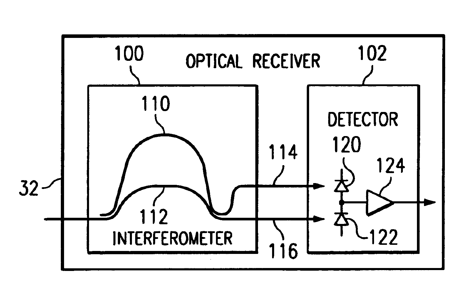
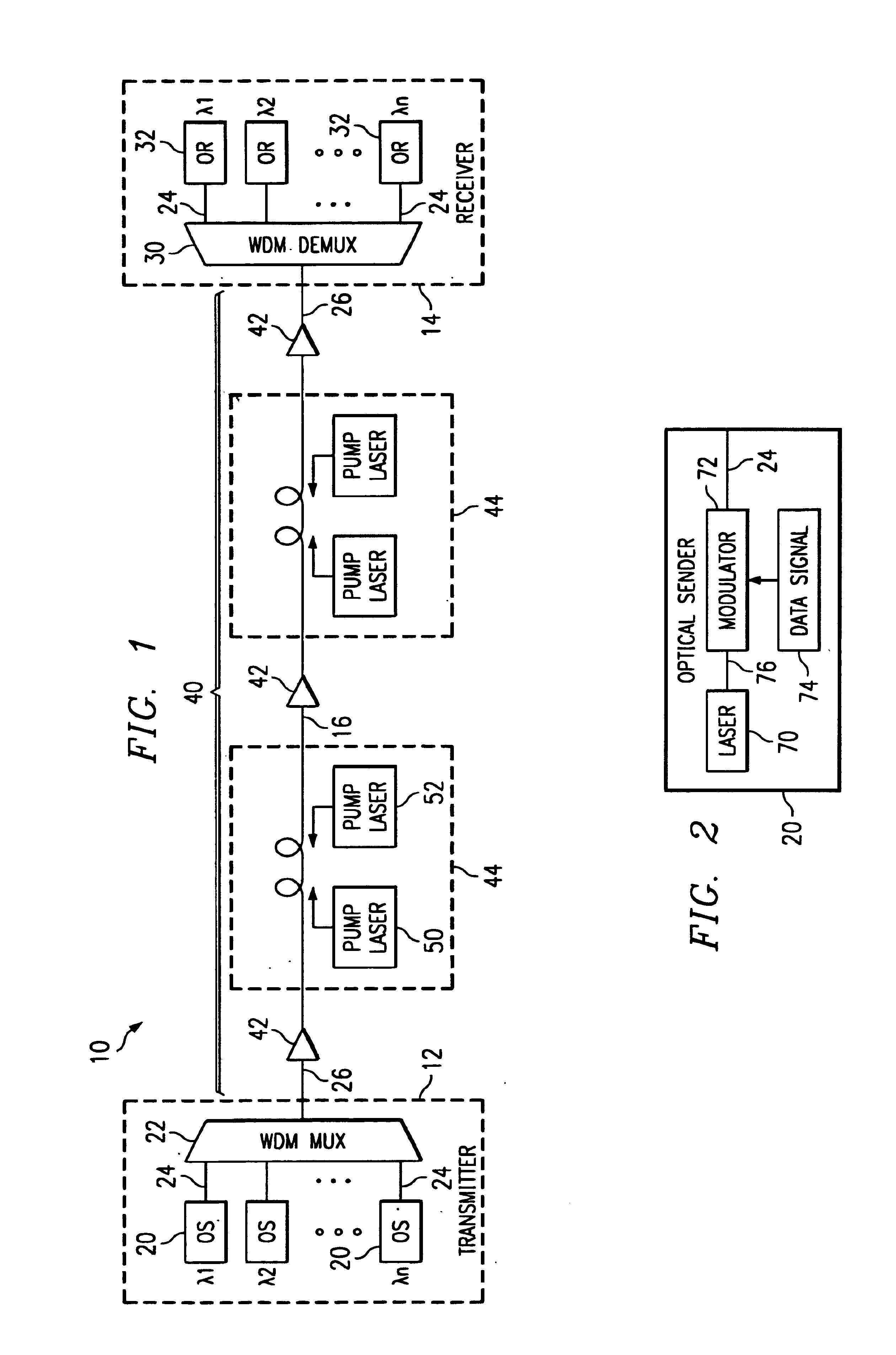
[0029]FIG. 1 illustrates an optical communication system 10 in accordance with one embodiment of the present invention. In this embodiment, the optical communication system 10 is a wavelength division multiplexed (WDM) system in which a number of optical channels are carried over a common path at disparate wavelengths. It will be understood that the optical communication system 10 may comprise other suitable single channel, multichannel or bi-directional transmission systems.

[0030]Referring to FIG. 1, the WDM system 10 includes a WDM transmitter 12 at a source end point and a WDM receiver14 at a destination end point coupled together by an optical link 16. The WDM transmitter 12 transmits data in a plurality of optical signals, or channels, over the optical link 16 to the remotely located WDM receiver 14. Spacing between the channels is selected to avoid or minimize cross talk between adjacent channels. In one embodiment, as described in more detail below, minimum channel spacing (d...


PUM


Abstract

A method and system for transmitting information in a wavelength division multiplex (WDM) or other suitable multichannel optical communication system includes receiving a multichannel signal having a symbol rate and comprising a plurality of non-intensity modulated optical information signals. The non-intensity modulated optical information signals have a minimum channel spacing comprising a multiple of the symbol rate within 0.4 to 0.6 of an integer. The non-intensity modulated optical information signals are separated from the multichannel signal and each converted into an intensity modulated optical information signal using an asymmetric interferometer. A data signal is recovered from the intensity modulated optical information signal.

Description

RELATED PATENT APPLICATIONS[0001]This application is related to U.S. patent application Ser. No. 09 / 853,323 entitled “Method and System for Transmitting Information in an Optical Communication System Using Distributed Amplification,” U.S. patent application Ser. No. 09 / 853,316 entitled “Method and System for Demultiplexing Non-Intensity Modulated Wavelength Division Multiplexed (WDM) Signals,” and U.S. patent application Ser. No. 09 / 853,340 entitled “Method and System for Tuning an Optical Signal Based on Transmission Conditions,” and U.S. patent application Ser. No. 09 / 853,319 entitled “Method and System for Communicating a Clock Signal Over an Optical Link, all filed on May 10, 2001.TECHNICAL FIELD OF THE INVENTION[0002]This invention relates generally to optical communication systems, and more particularly to a receiver and method for a multichannel optical communication system.BACKGROUND OF THE INVENTION[0003]Telecommunications systems, cable television systems and data communic...

Claims


Application Information

Patent Timeline
Patent Type & Authority Patents(United States)
IPC IPC(8): H04B10/06H04B10/02H04B10/04H04B10/08H04B10/142H04B10/152H04B10/158H04J14/00H04J14/02
CPCH04B10/0779H04B10/67H04B10/69H04J14/02
Inventor HOSHIDA, TAKESHI
Owner FUJITSU LTD
Why Eureka
Try Eureka