Determining the geographic location of a network device

a network device and geographic location technology, applied in the direction of location information based services, multi-programming arrangements, instruments, etc., can solve the problems of asymmetric routing, long delays, and many users not wanting to expend the effort necessary to type in addresses

Inactive Publication Date: 2007-04-03
RESOURCE CONSORTIUM LTD LLC
View PDF11 Cites 160 Cited by
  • Summary
  • Abstract
  • Description
  • Claims
  • Application Information

AI Technical Summary

Benefits of technology

[0025]By probing the routing path taken by an inbound data packet in the foregoing manner, the present invention often can identify the group of routers closest to the originator of the data packet in a relatively short period of time. By comparing the network identifier included in at least one of the probe responses to a database that includes a geographic location for each of multiple

Problems solved by technology

However, it is possible that the routing may be asymmetric, such as where a client computer transmits packets to an ISP over a conventional telephone line/modem connection but receives packets via a satellite dish, e.g., via the Direct PC network.
However, at present, both asymmetric routing and multi-path routing are considered to be unusual routing conditions.
Unfortunately, many users may not want to expend the effort necessary to type in address or even zip code information that identifies their geographic locations.
Moreover, even those that are willing to do so typically will find it very inconvenient, particularly when such infor

Method used


Image

  • Determining the geographic location of a network device
  • Determining the geographic location of a network device
  • Determining the geographic location of a network device

Examples


Embodiment Construction

)

[0031]The following discussion describes the preferred embodiments of the invention. Wherever possible, the same reference numbers are used throughout the drawings to refer to the same or like parts. The patent applications for “Creating a Geographic Database for Network Devices” and “Network Probing Using Overlapping Packets” filed by Steven Augart concurrently herewith are hereby incorporated by reference as though set forth herein in full.

Geographic Positioning.

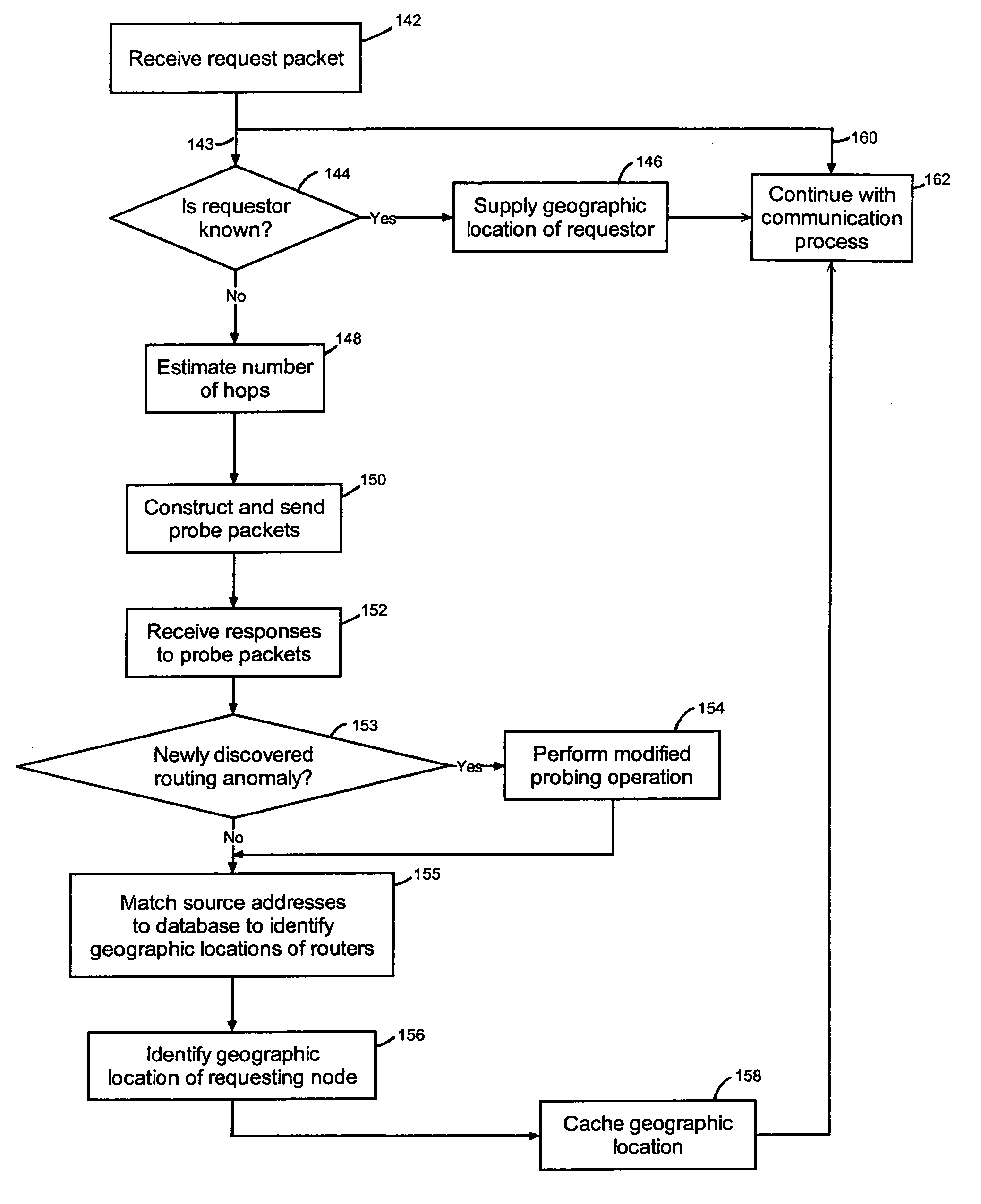
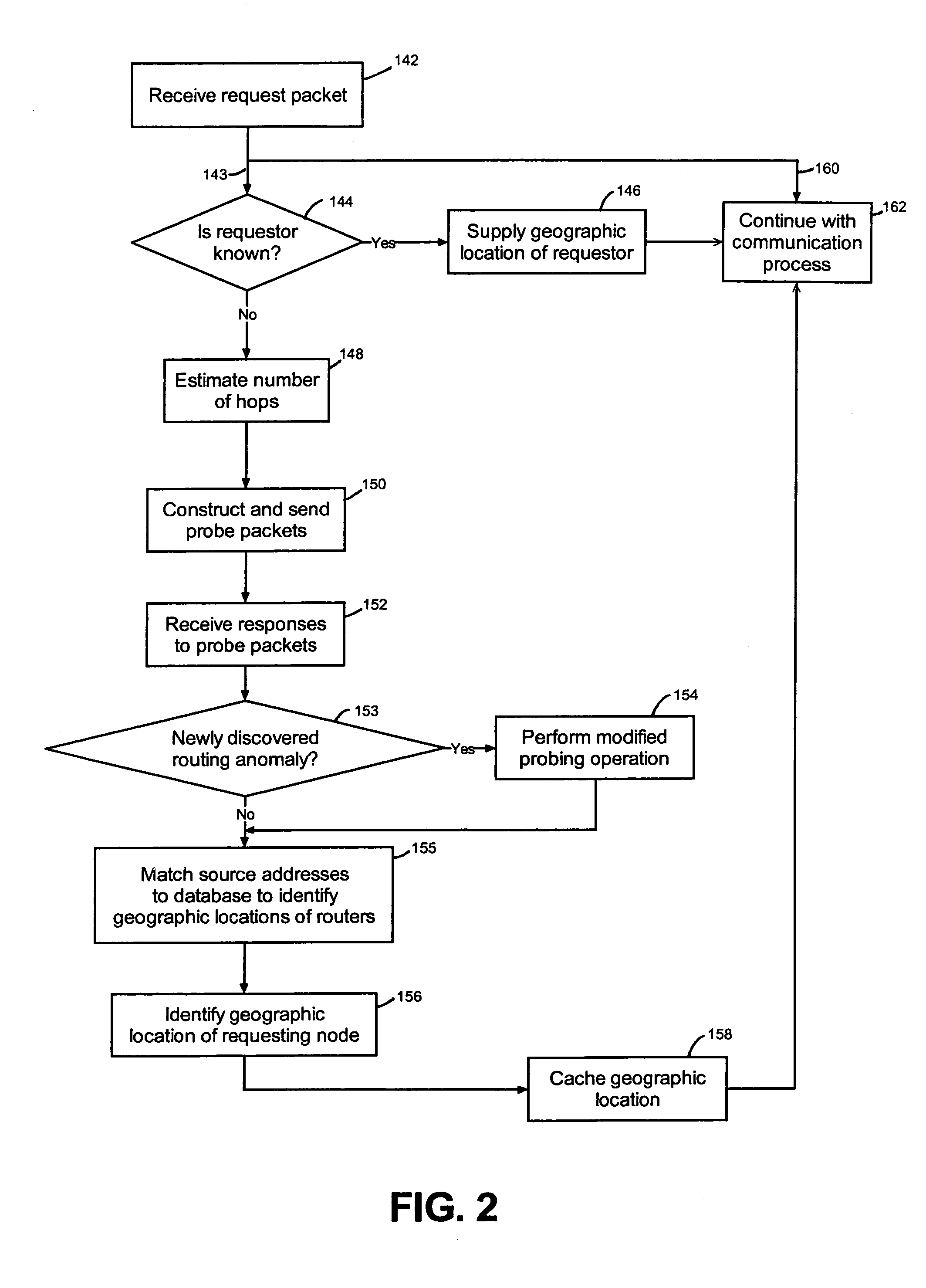
[0032]An overview of geographic positioning according to a representative embodiment of the invention will be described with reference to the flow diagram illustrated in FIG. 2. Briefly, according to FIG. 2, a request packet is received; if a geographic location has already been determined for the requestor, that geographic location is used as the location of the requestor; otherwise, the number of hops taken by the request packet is estimated, probe packets are constructed and sent, and responses to the probe packets are...


PUM


Abstract

Provided are techniques and apparatuses for determining the geographic location of a node on a network. In a representative embodiment, a data packet is received over the network from a second node, the data packet including a network identifier for the second node and a Time-To-Live (TTL) field that has a value, with the value of the TTL field for the data packet indicating a maximum additional number of hops that could have been made by the data packet. A probe packet addressed to the network identifier for the second node is then sent, the probe packet also including a TTL field. The initial value for the TTL field of the probe packet is set based on the value for the TTL field of the data packet.

Description

BACKGROUND OF THE INVENTION[0001]1. Field of the Invention[0002]The present invention concerns determining the geographic location of a network device, such as a device connected to the Internet.[0003]2. Description of the Related Art[0004]The Internet is a decentralized global network of millions computers. Each computer connected to the Internet is independent and may be capable of operating as a host computer (host) that primarily provides data over the Internet or a client computer (client) that primarily receives data over the Internet. A host computer may receive a data request from any other computer on the Internet and respond to the request by transmitting any of various types of data, such as hypertext markup language (HTML) code, back to the client. A client computer may send data requests to various hosts on the Internet and then download data in response. Typically, host computers are used by information providers for various commercial, educational, or governmental pur...

Claims


Application Information

Patent Timeline
IPC IPC(8): G06F15/173
CPCH04L41/12H04L45/02H04L45/20H04L45/26H04W4/02H04L67/18H04L41/16H04L67/52
Inventor AUGART, STEVEN
Owner RESOURCE CONSORTIUM LTD LLC
Why Eureka
Try Eureka