Highly linear variable gain amplifier

a variable gain, high-linear technology, applied in the direction of dc-amplifiers with dc-coupled stages, differential amplifiers, amplifiers with semiconductor devices/discharge tubes, etc., can solve the problems of serious corruption of desired signals, large amplitudes of interfering signals, so as to improve linearity and linearity greatly, the effect of improving the signal quality in the amplifier outpu

Active Publication Date: 2007-04-10
GCT SEMICONDUCTOR INC
View PDF4 Cites 14 Cited by
  • Summary
  • Abstract
  • Description
  • Claims
  • Application Information

AI Technical Summary

Benefits of technology

[0021]An object of the present invention is to provide a variable-gain amplifier which has improved linearity characteristics compared with other types of amplifiers which have been proposed.
[0022]Another object of the present invention is to achieve the aforementioned object by reducing the generation of harmonics and other forms of noise that cause distortion in the amplifier output.
[0023]Another object of the present invention is to achieve one or more of the aforementioned objects by eliminating common source node connections that serve as a principal source of nonlinear distortion in other variable-gain amplifiers which have been proposed.
[0024]Another object of the present invention is to achieve one or more of the aforementioned objects by eliminating common mode feedback circuitry which also serves as a principal source of nonlinear distortion in other variable-gain amplifiers which have been proposed.
[0033]The variable-gain amplifier of the present invention achieves improved linearity compared with other VGAs which have been proposed. These VGAs use a single differential operational amplifier which is non-ideal in terms of producing a linear characteristic and which also uses common mode feedback circuitry which has been shown to introduce noise into the amplifier output. The present invention overcomes these drawbacks by replacing the differential operational amplifier with two single-ended operational amplifiers, each of which is connected to receive a respective one of two differential input signals. Through this design, linearity is greatly improved and the use of common mode feedback circuitry can be avoided, both of which translate into improved signal quality in the amplifier output.

Problems solved by technology

Unfortunately, when these amplifiers lack sufficient linearity, the desired signal is corrupted by inter-modulation caused by strong interfering signals.
However, unlike FIG. 2, the interfering signals have significantly larger amplitudes than the desired signal.
Consequently, when amplified by a variable-gain amplifier having non-linear characteristics, the desired signal is seriously corrupted by noise terms generated from inter-modulation with the interfering signals.
If left uncompensated, this noise will propagate throughout the receiver to degrade the quality of the received signal.
In practice, however, the gain is not infinite and the amplifier suffers from secondary effects.
More specifically, since the amplifier is usually designed to have very high gain at its input stage, small distortion at the input stage generates large distortion at the output stage.
As a result, harmonics are generated at node A which alter the linear characteristics of the amplifier and thus generate the large distortion that occurs at the amplified output.
While this circuitry is beneficial for purposes of stabilizing the output levels of the amplifier, it produces mixed harmonics which cause distortions in the output signal.

Method used


Image

  • Highly linear variable gain amplifier
  • Highly linear variable gain amplifier
  • Highly linear variable gain amplifier

Examples


Embodiment Construction

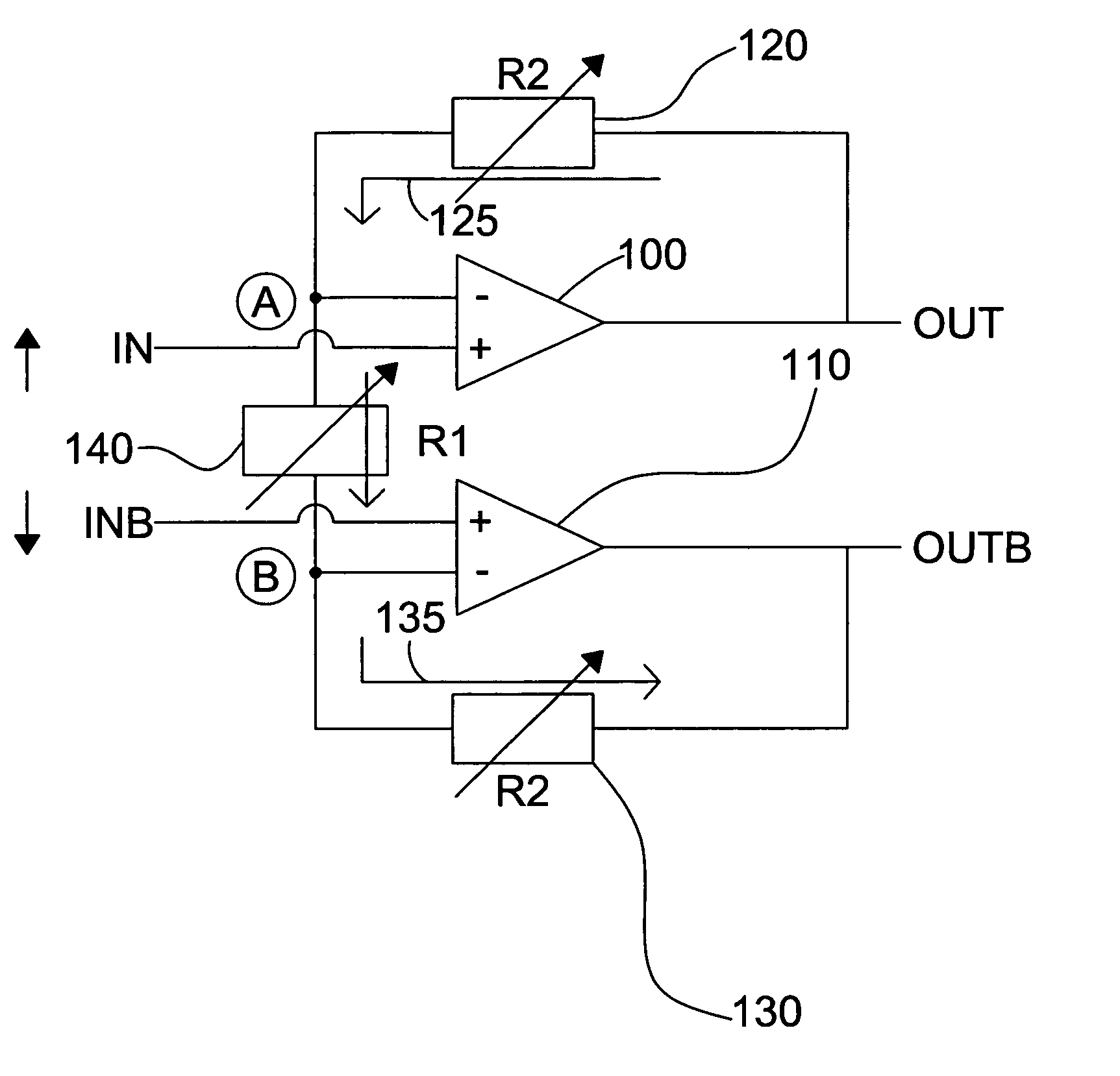
[0041]FIG. 6 shows a variable-gain amplifier in accordance with a preferred embodiment of the present invention. This amplifier includes first and second single-ended operational amplifiers 100 and 110 and three variable resistors 120, 130, and 140. The non-inverting terminals of the first amplifier and second amplifiers are connected to receive differential input signals IN and INB respectively. The inverting terminal of the first amplifier is connected to the output OUT of amplifier 100 through a feedback path which includes resistor 120, and the inverting terminal of the second amplifier is connected to the output OUTB of amplifier 110 through a feedback path which includes resistor 130. Resistors 120 and 130 preferably have the same resistance values.

[0042]The non-inverting of the first amplifier and the non-inverting terminal of the second amplifier are coupled to one another through resistor 140, which is preferably different in value from the other two resistors. More specifi...


PUM


Abstract

A variable-gain amplifier circuit uses a pair of single-ended operational amplifiers to amplify complementary portions of a differential input signal. By using two single-ended amplifiers instead of a single differential amplifier, linearity is significantly improved. In addition, common mode feedback circuitry is eliminated along with harmonic distortion and other forms of noise which tend to negative affect the quality of the signal output from the circuit.

Description

[0001]This application claims the benefit of priority of U.S. Provisional Patent Application No. 60 / 551,788, filed Mar. 11, 2004, entitled HIGHLY LINEAR VARIABLE GAIN AMPLIFIER.BACKGROUND OF THE INVENTION[0002]1. Field of the Invention[0003]The present invention generally relates to amplifying signals, and more particularly to a variable-gain amplifier and a method for controlling the same.[0004]2. Background of the Related Art[0005]Gain-controlled amplifiers are used in many wireless and wireline systems. In wireless applications, gain-controlled amplifiers which demonstrate a linear characteristic throughout a desired operational range are especially important for purposes of achieving a satisfactory level of performance.[0006]FIG. 1 shows one wireless application in the form of a cellular communications receiver, which includes variable-gain amplifiers along its signal path. The receiver includes an antenna 1, an RF bandpass filter 2, and a low-noise amplifier 3. The signal outpu...

Claims


Application Information

Patent Timeline
Patent Type & Authority Patents(United States)
IPC IPC(8): H03F3/45H03F3/21
CPCH03F3/211H03F3/45475H03F3/45659H03F2203/45136H03F2203/45138H03F2203/45166H03F2203/45168H03F2203/45434H03F2203/45522H03F2203/45591H03F3/45H03F1/32
Inventor PARK, JOONBAELEE, SEUNG-WOOKLEE, JEONG-WOOLEE, KYEONGHO
Owner GCT SEMICONDUCTOR INC
Why Eureka
Try Eureka