Lithographic printing with printing members having primer layers

a technology of printing members and printing members, applied in thermography, instruments, photosensitive materials, etc., can solve the problems of insufficient ink retention of silicone-surfaced dry plates by exposed ink-receptive layers, inability to observe certain performance limitations, and complex source of ink retention behavior, etc., to improve print-making performance and efficiency, and inhibit production

Inactive Publication Date: 2007-04-17
MARK ANDY
View PDF20 Cites 10 Cited by
  • Summary
  • Abstract
  • Description
  • Claims
  • Application Information

AI Technical Summary

Benefits of technology

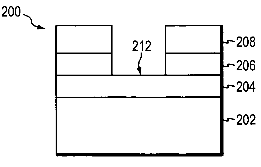
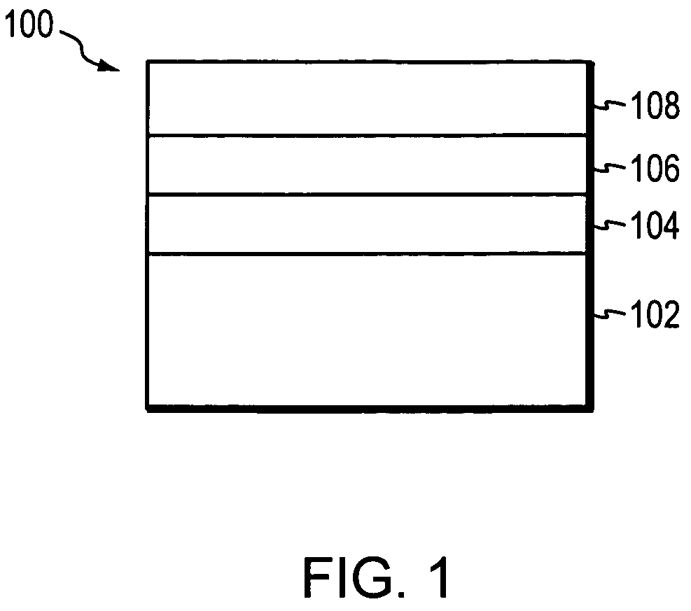
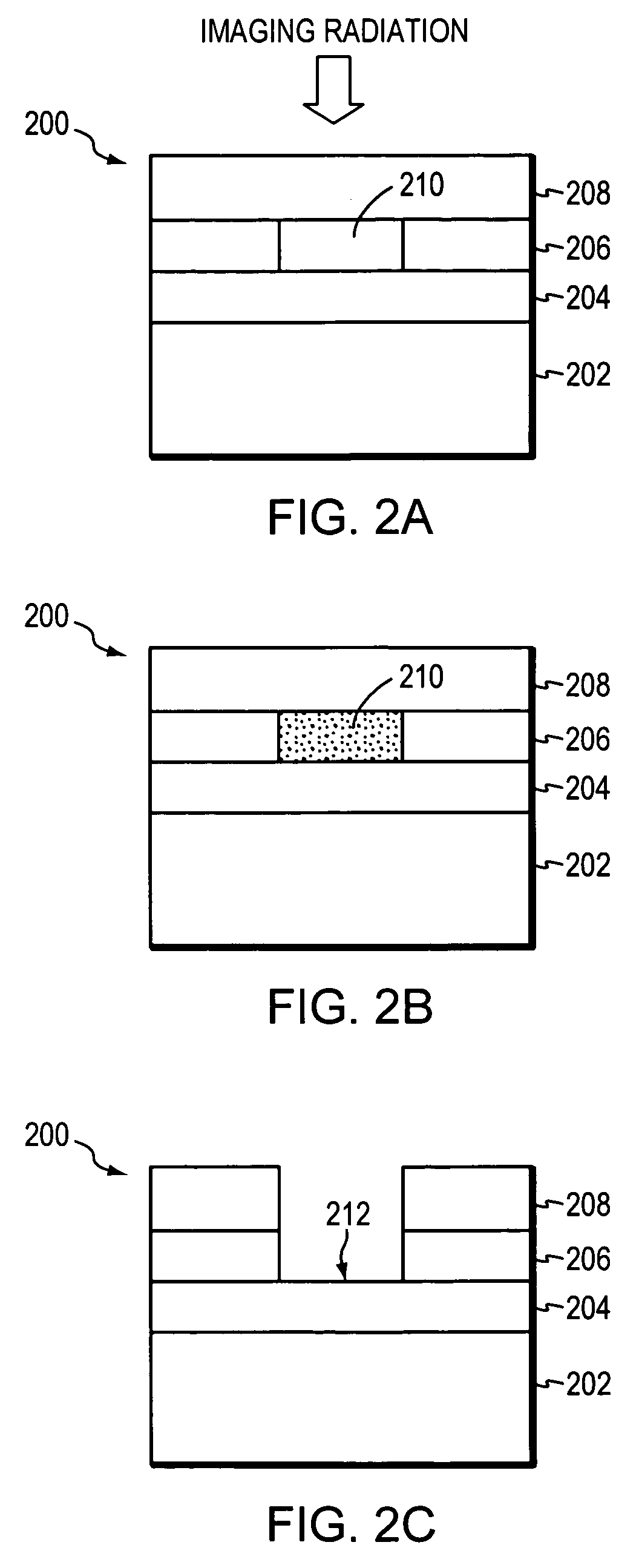
[0007]The present invention utilizes a primer layer disposed between the imaging layer and the substrate of a lithographic printing member. The primer layer inhibits the production of thermal degradation products that disrupt the oleophilicity of the exposed imaged areas, thereby improving print-making performance and efficiency. In addition, embodiments of the primer layer inhibit static charge buildup during production and during the print-making process.

Problems solved by technology

Depending on the particular printing member and imaging conditions, certain performance limitations may be observed.
For example, a silicone-surfaced dry plate may exhibit insufficient retention of ink by the exposed ink-receptive layer.
The source of this behavior, however, is complex; it does not arise merely from stubbornly adherent silicone fragments.
Nonetheless, such plates still may print with the inferior quality associated with inadequate affinity for ink.
Similar limitations may be observed in wet lithographic printing members having hydrophilic surface layers disposed over oleophilic sublayers.
Because the metal imaging layer is in contact with the chemically complex silicone layer, the high temperatures attained during imaging can induce unwanted thermal reactions that produce silicone-derived products.
That surface, moreover, is also rendered more vulnerable to interaction with silicone breakdown products as a result of exposure to high temperatures, which can melt and thermally degrade the surface of the substrate so that it readily accepts breakdown products.
In both dry and wet plate constructions, the adhesion, implantation, mechanical intermixture, and chemical reaction of breakdown products from the surface layer with the underlying oleophilic layer(s) interferes with the printing member's ability to retain ink.
This can lead to static discharge which poses health and safety hazards.
Spark discharges can jump from one conductive non-image area to another, causing non-conductive image areas to ablate post-imaging, thus creating additional unwanted ink-receptive areas.

Method used


Image

  • Lithographic printing with printing members having primer layers
  • Lithographic printing with printing members having primer layers
  • Lithographic printing with printing members having primer layers

Examples


example 1

[0056]The following experiments illustrate the effect that increasing amounts of surface-tension modifier in the polymeric binder has on the surface tension and roughness of primer layers according to the invention. Six dry lithographic plates were constructed according to the invention, each plate including a polyester substrate, a primer layer made of a cellulose acetate propionate (CAP) binder having various weight % of TiO2 particles dispersed therein, a titanium metal imaging layer, and a silicone surface layer. The ratio of TiO2 to CAP for each plate is listed in Table 1 below.

[0057]Each plate was imaged on a Dimension 400 imager (Presstek, Inc., Hudson, N.H.), and the imaging residue was removed by machine cleaning (Javin Machine Corp, West Babylon, N.Y.). The surface tension of the imaged areas of each plate were then measured using standard techniques with solutions containing formamide and either 2-ethoxyethanol or reagent grade water (Diversified Enterprises, Claremont, N...

example 2

[0061]The following experiments illustrate the effect that primer layers according to the invention have on the time it takes to achieve a target average ink density (i.e., roll-up time). Four dry lithographic plates were constructed as follows:

[0062]

ImagingSurfaceSubstratePrimer LayerLayerLayerPlate 7PolyesterNonetitaniumsiliconePlate 8Polyester3:1 SiO2 / nitrocellulosetitaniumsiliconePlate 9Polyester2:1 Zelec ECP 3010titaniumsilicone(antimony-doped tinoxide, Milliken Chemical,Spartanburg, SC) / celluloseacetate butyratePlate 10Polyester3:1 TiO2 / cellulosetitaniumsiliconeacetate butyrate

[0063]Each plate was imaged on a Dimension 400 imager (Presstek, Inc., Hudson, N.H.). Immediately after imaging, 1000 prints were produced from each plate using Toyo ink (Toyo Ink, Addison, Ill.), and the ink densities of the prints were measured at set intervals. Ink densities were measured using a Macbeth Status T densitometer (Amazys Holding AG, Regensdorf, Switzerland) in a solid area in the same pos...

example 3

[0066]The following experiments investigated the effect that primer layers according to the invention have on roll-up time using a different ink. Four dry lithographic plates were constructed according to Example 2 above, and each plate was imaged using a Dimension 400 imager (Presstek, Inc., Hudson, N.H.). Immediately after imaging, 500 prints were produced from each plate using K&E ink (BASF, Mount Olive, N.J.), and the average ink density of the prints were measured at set intervals using a Macbeth Status T densitometer (Amazys Holding AG, Regensdorf, Switzerland), as discussed above. The results of the experiments are summarized in FIG. 6 and Table 3 below.

[0067]

TABLE 3Ink DensitySheet #Plate 7Plate 8Plate 9Plate 10100.121.221.221.34500.511.191.221.241000.831.201.231.211501.101.201.231.242501.261.201.211.275001.201.211.221.27

[0068]As FIG. 6 and Table 3 indicate, the three primer coated plates (i.e., Plates 8–10) appeared to reach a high average ink density within the first 50 sh...


PUM

PropertyMeasurementUnit
Raaaaaaaaaaa
surface tensionaaaaaaaaaa

Abstract

A primer layer that includes a surface-tension modifier dispersed within a polymer binder is disposed between the imaging layer and the substrate of a lithographic printing member to inhibit the production of thermal degradation products that disrupt the oleophilicity of the exposed imaged areas, thereby improving print-making performance and efficiency. In addition, embodiments of the primer layer inhibit static charge buildup during production and during the print-making process.

Description

CROSS-REFERENCE TO RELATED APPLICATIONS[0001]The present application claims priority to and the benefit of U.S. provisional application Ser. No. 60 / 568,344, filed on May 5, 2004, the disclosure of which being incorporated by reference herein.BACKGROUND OF THE INVENTION[0002]In offset lithography, a printable image is present on a printing member as a pattern of ink-accepting (oleophilic) and ink-rejecting (oleophobic) surface areas. Once applied to these areas, ink can be efficiently transferred to a recording medium in the imagewise pattern with substantial fidelity. Dry printing systems utilize printing members whose ink-repellent portions are sufficiently phobic to ink as to permit its direct application. In a wet lithographic system, the non-image areas are hydrophilic, and the necessary ink-repellency is provided by an initial application of a dampening fluid to the plate prior to inking. The dampening fluid prevents ink from adhering to the non-image areas, but does not affect...

Claims


Application Information

Patent Timeline
Patent Type & Authority Patents(United States)
IPC IPC(8): G03F7/14G03F7/11B41C1/10B41N1/00B41N1/14B41N3/00
CPCB41C1/1016B41C1/1033B41N1/003B41N1/14B41C2201/04Y10S430/165B41C2210/266B41C2201/14B41C2210/02B41C2210/04B41C2210/08B41C2210/24B41C2201/02
Inventor CASSIDY, KENNETH R.
Owner MARK ANDY
Why Eureka
Try Eureka