Method of loading beneficial agent to a prosthesis by fluid-jet application

a technology of beneficial agents and prostheses, applied in the field of fluid-jet application of beneficial agents to prostheses, can solve the problems of re-narrowing of an artery, blood vessel acute occlusion, variability in drug loading across an interventional device,

Inactive Publication Date: 2007-04-24
ABBOTT LAB INC
View PDF43 Cites 82 Cited by
  • Summary
  • Abstract
  • Description
  • Claims
  • Application Information

AI Technical Summary

Benefits of technology

[0023]In yet another aspect of the invention, the method further includes the step of applying a solvent onto the prosthesis to redistribute the beneficial agent dispensed onto the predetermined portion by the dispensing step. A method is also provided further including the steps of providing a second beneficial agent to be delivered from the prosthesis; providing a second dispensing element capable of dispensing a second beneficial agent in discrete droplets along a controlled trajectory; creating relative movement between the second dispensing element and the prosthesis along a second dispensing path; and dispensing the second beneficial agent from the second dispensing element to a second predetermined portion of the prosthesis along the second dispensing path.
[0027]In another aspect of the invention, a method of loading beneficial agent onto a prosthesis for delivery within a lumen is provided, the method comprising the steps of providing a prosthesis to be deployed within a lumen, the prosthesis having a surface; providing beneficial agent to be delivered from the prosthesis; applying a layer of base material on at least a section of the surface of the prosthesis; providing a fluid-dispenser having a dispensing element capable of dispensing discrete droplets of beneficial agent along a controlled trajectory; creating relative movement between the dispensing element and the prosthesis to define a dispensing path for dispensing beneficial agent in a raster format; and dispensing beneficial agent selectively from the dispensing element to a predetermined portion of the base material layer along the dispensing path.

Problems solved by technology

While PTCA is widely used, it suffers from two unique problems.
First, the blood vessel may suffer acute occlusion immediately after or within the initial hours after the dilation procedure.
The second problem associated with this procedure is the re-narrowing of an artery after an initially successful angioplasty.
However, some problems associated with such drug eluting interventional devices is the variability in drug loading across an interventional device, as well as the variability in drug concentration from device to device.
Other disadvantages include the inability to tightly control and maintain drug concentration, the inability to verify drug distribution or drug loading on any given device, the inability to vary drug distribution in a controlled and predetermined manner to effect a more desirable drug loading profile, the inability to load different, and in particular incompatible or reactive drugs onto the same surface of a device, and the difficulty in controlling the local areal density of beneficial agent that is delivered to the lumen, particularly if the interventional device is an overlapping or bifurcated device coated with beneficial agent.
Because certain interventional devices may have a varied surface area along its length, such conventional loading techniques results in unintentional or undesirable dosage variations.
Another drawback of the conventional methods of loading interventional devices with beneficial agents is the lack of selective dosing, such as providing various beneficial agents or various concentrations of the same beneficial agent at different locations on a prosthesis to effect a therapy at specific targeted sites.

Method used


Image

  • Method of loading beneficial agent to a prosthesis by fluid-jet application
  • Method of loading beneficial agent to a prosthesis by fluid-jet application
  • Method of loading beneficial agent to a prosthesis by fluid-jet application

Examples


example 1

Jetting of Reactive Substances

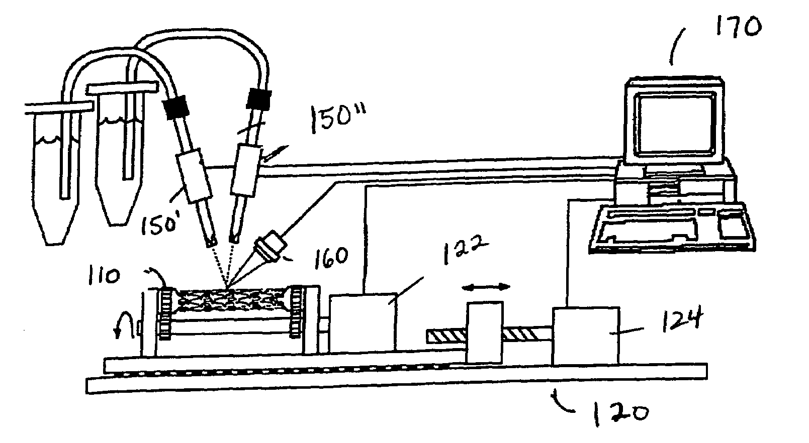
[0141]The components of a commercial two-part epoxy formulation are mixed by the jetting process and applied to a surface to form a coating. In a formulation manufactured by Buehler, Lake Bluff Ill., one part is a liquid “epoxide resin” that contains 4,4′ isopropylidenediphenol epichlorohydrin resin and butyl glycidyl ether. The second part is a liquid “hardener” that contains diethylene triamine, triethylene tetramine, and polyoxypropylenediamine. In the jetting process, one reagent jet system (A) is loaded with epoxide resin and a second jetting system (B) is loaded with hardener The jets are aligned such that the droplets emanating from each jet combine in midair and travel to the target device to form a crosslinked coating, after a curing time of 2–8 hours. The volume of a droplet emanating from jet A is 5 times larger than the volume of a droplet emanating from Jet B and the total number of droplets dispensed from each jet are approximately equal.

example 2

Jetting of Reactive Substances

[0142]The components of a commercial two-part epoxy formulation are mixed by the jetting process and applied to a surface to form a coating. In a two part commercial formulation manufactured by Buehler, Lake Bluff Ill., one part is a liquid “epoxide resin” which contains 4,4′ isopropylidenediphenol epichlorohydrin resin and butyl glycidyl ether. The second part is a liquid “hardener” that contains diethylene triamine, triethylene tetramine, and polyoxypropylenediamine. In the jetting process, one reagent jet system (A) is loaded with epoxide resin and a second jetting system (B) is loaded with hardener. The jets are aligned such that the droplets emanating from each jet combine in midair and travel to the target device to form a crosslinked coating, after a curing time of 2–8 hours. The volume of a droplet emanating from jet A is 4 times larger than the volume of a droplet emanating from Jet B and the total number of droplets dispensed from each jet are...

example 3

Jetting of Reactive Substances

[0143]The components of a commercial two-part epoxy formulation are mixed by the jetting process and applied to a surface to form a coating. In a two part commercial formulation manufactured by Buehler, Lake Bluff Ill., one part is a liquid “epoxide resin” which contains 4,4′ isopropylidenediphenol epichlorohydrin resin and butyl glycidyl ether. The second part is a liquid “hardener” that contains diethylene triamine, triethylene tetramine, and polyoxypropylenediamine. In the jetting process, one reagent jet system (A) is loaded with epoxide resin and a second jetting system (B) is loaded with hardener. The jets are aligned such that the droplets emanating from each jet combine in midair and travel to the target device to form a crosslinked coating, after a curing time of 2–8 hours. The volume of a droplet emanating from jet A is approximately equal to the volume of a droplet emanating from Jet B, but the total number of droplets dispensed from jet A is...


PUM

PropertyMeasurementUnit
diametersaaaaaaaaaa
diameteraaaaaaaaaa
diameteraaaaaaaaaa

Abstract

An interventional device for delivery of beneficial agent to a lumen and methods of loading and manufacture of the same, which include a prosthesis loaded with beneficial agent to provide a controlled dosage concentration of beneficial agent to the lumen. The beneficial agent is loaded onto the prosthesis by a fluid-dispenser having a dispensing element capable of dispensing the beneficial agent in discrete droplets, each droplet having a controlled trajectory. The method of loading beneficial agent includes dispensing beneficial agent in a raster format and / or an off-axis format along a dispensing path.

Description

RELATED APPLICATIONS[0001]This application claims the benefit of U.S. Provisional Patent Applications Ser. Nos. 60 / 424,574; 60 / 424,575; 60 / 424,576; 60 / 424,577; and 60 / 424,607, each of which was filed on Nov. 7, 2002, and each of which is incorporated herein by reference thereto.BACKGROUND OF THE INVENTION[0002]1. Field of the Invention[0003]The present invention relates to a method and system for loading beneficial agent onto a prosthesis using a fluid-dispenser having a dispensing element capable of dispensing beneficial agent in discrete droplets, each droplet having a controlled trajectory. The method in particular relates to a method of dispensing beneficial agent in a raster format and / or an off-axis format along a dispensing path.[0004]2. Description of Related Art[0005]Percutaneous transluminal coronary angioplasty (PTCA) is a procedure for treating heart disease. This procedure generally entails introducing a catheter assembly into the cardiovascular system of a patient via ...

Claims


Application Information

Patent Timeline
Patent Type & Authority Patents(United States)
IPC IPC(8): A61L27/54A61F2/00A61F2/06B05C5/02B05C13/02B65D30/00E02B3/12
CPCA61F2/91A61F2/915E02B3/127B05C5/0216B05C13/025A61F2002/065A61F2002/067A61F2002/91525A61F2002/91575A61F2250/0067A61F2250/0068A61F2002/91533A61F2250/0098A61F2210/0004A61P31/04A61P35/00A61P7/02B05C5/02A61L27/54A61F2/07A61L27/14A61F2/852A61F2/958A61F2002/825A61F2002/826A61F2002/91558A61F2002/91566G11B7/00
Inventor VERLEE, DONALDTARCHA, PETERCROMACK, KEITHQUINT, RICHARD
Owner ABBOTT LAB INC
Why Eureka
Try Eureka