Variable speed drive for a chiller system

a chiller system and variable speed technology, applied in the direction of electric controllers, dynamo-electric converter control, instruments, etc., can solve the problems of limited ability to withstand temporary voltage sags of several seconds when operating at speeds close to maximum, limited ability to modulate the capacity of the compressor to less efficient mechanical devices, and limited prior induction motor style vsds in their ability, etc., to achieve the effect of reducing motor and inverter losses, increasing system efficiency

Active Publication Date: 2007-04-24
JOHNSON CONTROLS TYCO IP HLDG LLP
View PDF57 Cites 21 Cited by
  • Summary
  • Abstract
  • Description
  • Claims
  • Application Information

AI Technical Summary

Benefits of technology

[0010]One advantage of the present invention is increased system efficiency and potential cost reduction by eliminating gears between the motor and the compressor.
[0011]Another advantage of the present invention is a reduction in motor and inverter losses.
[0012]A further advantage of the present invention is improved reliability of the chiller system.
[0013]Another advantage of the present invention is improved input power quality in the variable speed drive.
[0014]Still another advantage of the present invention is that the variable speed drive has improved ride-through capabilities during input voltage sags.

Problems solved by technology

The use of line voltages and frequencies typically limited the options for modulating the capacity of the compressors to less efficient mechanical devices such as inlet guide vanes and slide valves, as a result of the motor being limited to one operating speed that was based on the input frequency to the motor.
One limitation of prior induction motor style VSDs was that the magnitude of the fundamental output voltage from the VSD could be no larger than the magnitude of the input, or utility, line voltage to the VSD without creating an excessive amount of harmonic voltage.
This limitation on the output voltage of the variable speed drive limits the maximum speed of the conventional induction motor to a speed that corresponds to the speed of the motor operated at line voltage if constant volts / hertz ratio operation (also known as constant flux operation) was required.
Prior induction motor style VSDs are also limited in their ability to provide ride-through capability that enables them to withstand temporary sags on the input line voltage.
The ability to withstand such temporary voltage sags of several seconds when operating at speeds close to maximum were thus limited, since the output voltage of the VSD is dependent upon the magnitude of the DC Link voltage, and thus the input voltage.
In addition, this limitation on the output voltage from the VSD limited the operating efficiency of high speed induction motors in the chiller system.
The high speed motors, used to obtain faster compressor speeds without the “step up” gearing arrangement, were limited because it is more difficult to design an efficient and cost-effective motor when a reduced maximum operating voltage was available at the maximum operating speed.

Method used


Image

  • Variable speed drive for a chiller system
  • Variable speed drive for a chiller system
  • Variable speed drive for a chiller system

Examples


Embodiment Construction

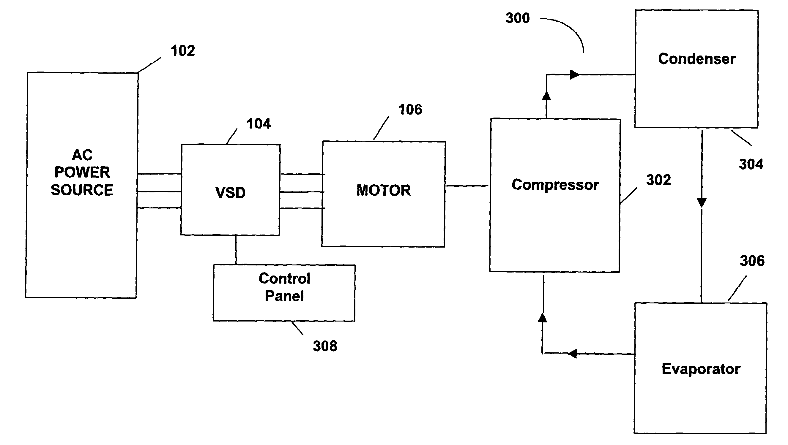
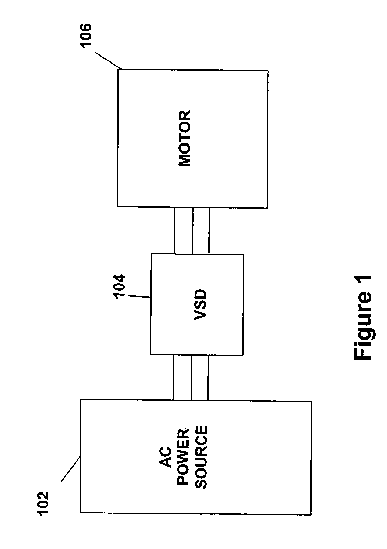
[0021]FIG. 1 illustrates generally the system configuration of the present invention. An AC power source 102 supplies AC power to a variable speed drive (VSD) 104, which in turn, supplies AC power to a motor 106. In another embodiment of the present invention, the VSD 104 can power more than one motor. The motor 106 is preferably used to drive a corresponding compressor of a refrigeration or chiller system (see generally, FIG. 3). The AC power source 102 provides single phase or multi-phase (e.g., three phase), fixed voltage, and fixed frequency AC power to the VSD 104 from an AC power grid or distribution system that is present at a site. The AC power grid can be supplied directly from an electric utility or can be supplied from one or more transforming substations between the electric utility and the AC power grid. The AC power source 102 can preferably supply a three phase AC voltage or nominal line voltage of 200 V, 230 V, 380 V, 460 V, or 600 V, at a nominal line frequency of 5...


PUM


Abstract

A variable speed drive with a boost converter is provided for a chiller system driven by an induction motor. The boost converter can be a diode or thyristor rectifier followed by a boost DC / DC converter or a three-phase pulse width modulated boost converter. The boost converter provides a boosted voltage to the DC link, which results in a boosted voltage being applied to the induction motor by the inverter of the variable speed drive.

Description

BACKGROUND OF THE INVENTION[0001]The present invention relates generally to a variable speed drive for a chiller system. More specifically, the present invention relates to a variable speed drive with boost capability for a variable speed chiller system.[0002]In the past, the motors for driving compressors in chiller systems were designed to operate from standard line (main) voltages and frequencies that were available from the power distribution system of the facility where the motor was being operated. The use of line voltages and frequencies typically limited the options for modulating the capacity of the compressors to less efficient mechanical devices such as inlet guide vanes and slide valves, as a result of the motor being limited to one operating speed that was based on the input frequency to the motor. In addition, if the operating speed of the motor was not equal to the desired operating speed of the compressor, a “step up,” or “step down,” gearbox was inserted between the...

Claims


Application Information

Patent Timeline
Patent Type & Authority Patents(United States)
IPC IPC(8): H02P1/42H02P23/00
CPCB60H1/00428H02P27/08H02P2201/09Y02T10/88H02P1/46H02M7/48
Inventor JADRIC, IVANSCHNETZKA, HAROLD ROBERT
Owner JOHNSON CONTROLS TYCO IP HLDG LLP
Why Eureka
Try Eureka