Polarizing electrode, manufacturing method thereof, and electric double-layer capacitor

a technology of double-layer capacitors and polarizing electrodes, applied in the direction of electrolytic capacitors, cell components, hybrid cases/housings/encapsulations, etc., can solve the problems of double-layer capacitors not being able to offer a sufficient performance, unable to carry out a function, and unable to meet the requirements of the application

Inactive Publication Date: 2007-04-24
JAPAN SCI & TECH CORP +1
View PDF10 Cites 15 Cited by
  • Summary
  • Abstract
  • Description
  • Claims
  • Application Information

AI Technical Summary

Problems solved by technology

However, a conventional electric double-layer capacitor cannot supply a large current in an instant so that it cannot carry out a function which is required to serve as a power supply for the pulse power.
As a result, the conventional electric double-layer capacitor involves a problem such that, when a large current is discharged, a capacity is decreased by appearance and the conventional electric double-layer capacitor cannot sufficiently offer a performance.

Method used


Image

  • Polarizing electrode, manufacturing method thereof, and electric double-layer capacitor
  • Polarizing electrode, manufacturing method thereof, and electric double-layer capacitor
  • Polarizing electrode, manufacturing method thereof, and electric double-layer capacitor

Examples


embodiments

(Embodiments)

[0031]Hereinafter, the embodiments of a polarizing electrode according to the present invention, a manufacturing method thereof, and an electric double-layer capacitor using it will be described.

example 1

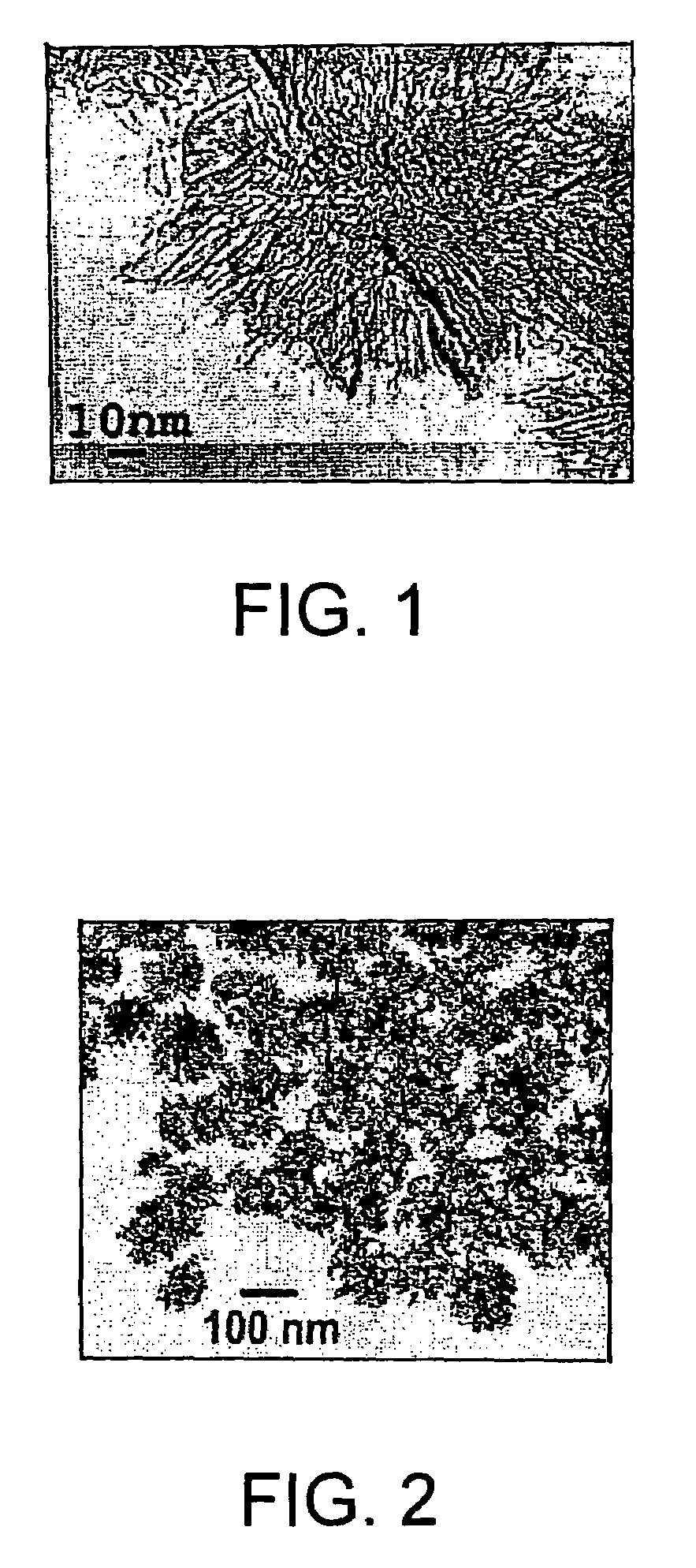
[0032]At first, a single-layer carbon nanohorn aggregate was manufactured by a laser ablation method targeting graphite in an inactive gas atmosphere of 760 Torr at a room temperature, and then, the manufactured carbon nanohorn aggregate was treated with a nitricacid solution. Consequently, mixing the single-layer carbon nanohorn aggregate treated with the nitricacid solution with a heat fusible and heat hardening phenol resin powder (a bellpearl S-type, made by Kanebo Corporation) at a weight ratio of 7:3, further, a dry blending was carried out by a ball mill. In the meantime, the single-layer carbon nanohorn aggregate used here is a single-layer carbon nanohorn aggregate composed of single-layer carbon nanohorns. Then, a specific surface area of this single-layer carbon nanohorn aggregate was 1,300 m2 / g.

[0033]Dividing the mixture powders made as described above into 10 g each, and molding them at 150° C., at a pressure of 100 kg / cm2, for ten minutes, a plurality of single-layer c...

example 2

[0041]At first, in the same way as the example 1, the single-layer carbon nanohorn aggregate was made according to the laser ablation method, and it was treated with the nitricacid solution. Then, by placing the single-layer carbon nanohorn aggregate treated with the nitricacid solution in a vacuum of 1×10⁻³ Torr together with a carbon nanofiber, and providing a heat treatment to them, a front end of the single-layer carbon nanohorn aggregate was fused (supported) by the carbon nanofiber. The specific surface area of the material allowing this single-layer carbon nanohorn aggregate supported by the carbon nanofiber was 1,350 m2 / g.

[0042]As same as the example 1, after mixing the above-described material with the phenol resin powder at a weight ratio of 7:3, further, the dry blending was carried out by the ball mill. Then, dividing the mixture powders into 10 g each, and molding them at 150° C., at a pressure of 100 kg / cm2, for ten minutes, the single-layer carbon nanohorn aggregates / ...


PUM

PropertyMeasurementUnit
specific surface areaaaaaaaaaaa
diameteraaaaaaaaaa
diameteraaaaaaaaaa

Abstract

An electric double-layer capacitor includes a carbon composite electrode which serves as a polarizing electrode and made of a single-layer carbon nanohorn aggregate having a specific structure and a very large surface area. The single carbon nanohorn aggregate is mixed with a phenol resin, the mixture is formed and heated to produce a carbon composite electrode. The carbon composite electrode is impregnated with an electrolyte to become a polarizing electrode. An electric double-layer capacitor includes this polarizing electrode has a large capacitance and is capable of discharging with large current.

Description

CROSS-REFERENCE TO RELATED APPLICATION[0001]The present application is a continuation of and claims priority uinder 35 USC § 120 from International PCT Application No. PCT / JP02 / 09953, filed on Sep. 26, 2002 which claims priority under 35 USC § 119 from Japanese Patent Application Number 294769 / 2001 filed on Sep. 26, 2001.TECHNICAL FIELD[0002]The present invention relates to an electric double-layer capacitor and, more particularly, the present invention relates to a polarizing electrode to be used therefor.BACKGROUND ART[0003]The electric double-layer capacitor uses a pair of electric charge layers (electric double-layer capacitor) each of which having different codes and which is generated on a boundary between a conductive material composing an electrode and an electrolyte impregnated in the conductive material; and the electric double-layer capacitor is characterized by not causing deterioration which occurs as a result of charge and discharge. Therefore, for example, the electri...

Claims


Application Information

Patent Timeline
Patent Type & Authority Patents(United States)
IPC IPC(8): H01G9/00B82Y99/00C01B31/02H01G11/22H01G11/24H01G11/30H01G11/34H01G11/36H01G11/40H01G11/44H01G11/78H01G11/80H01G11/84H01G11/86H01M4/36
CPCH01G9/155H01M4/583H01M4/364Y02E60/13Y02E60/10H01G11/34H01G11/36H01G11/38H01G11/86H01G11/44
Inventor YOSHITAKE, TSUTOMUIIJIMA, SUMIOYUDASAKA, MASAKO
Owner JAPAN SCI & TECH CORP
Why Eureka
Try Eureka