Speaker

a loudspeaker and speaker technology, applied in the field of loudspeakers, can solve the problems of difficult to improve non-linearity and asymmetry in the conventional loudspeaker, and achieve the effects of improving power linearity, reducing harmonic distortion, and increasing performan

Active Publication Date: 2007-04-24
PANASONIC CORP
View PDF9 Cites 25 Cited by
  • Summary
  • Abstract
  • Description
  • Claims
  • Application Information

AI Technical Summary

Benefits of technology

[0005]An object of the present invention is to provide a novel arrangement for a loudspeaker which is able to reduce harmonic distortion and improve power linearity and thereby provide increased performance. A loudspeaker according to the present invention comprises: a magnetic circuit including a magnetic gap; a voice coil member disposed in the magnetic gap of the magnetic circuit and having a movable coil; a diaphragm whose inner peripheral part is linked with the voice coil member outside the magnetic gap; and a frame linked with an outer peripheral part of the diaphragm via a first edge; wherein an inner peripheral part of a suspension holder is linked with the voice coil member at a linked position which is closer to the magnetic circuit than the linked position of the diaphragm and the voice coil member; wherein an outer peripheral part of the suspension holder is linked with the frame via a second edge; and wherein the first edge and the second edge are substantially symmetrical with each other about a median of the first edge and the second edge.
[0006]The structure mentioned above does not require a damper, thereby providing a loudspeaker for solving the problems of non-linearity and asymmetry of a suspension.

Problems solved by technology

As a result, it is difficult to improve non-linearity and asymmetry in the conventional loudspeaker, so that harmonic distortion is not reduced.

Method used


Image

  • Speaker
  • Speaker
  • Speaker

Examples


first exemplary embodiment

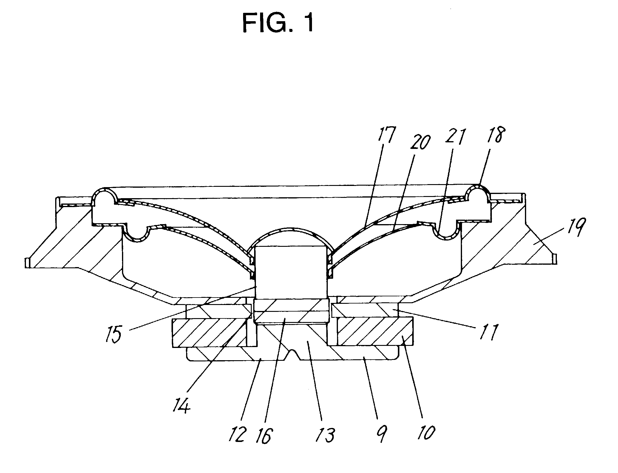
[0032]FIG. 1 is a sectional view of a loudspeaker in accordance with the first exemplary embodiment of the present invention. A magnetic circuit 9 is formed of a ring-shaped magnet 10, ring-shaped plate 11, disk-shaped yoke 12 and columnar pole 13. Magnetic flux of the magnet 10 is concentrated in a magnetic gap 14 between an inner peripheral part of the plate 11 and an outer peripheral part of the pole 13.

[0033]Ferromagnetic material, such as a ferrite base magnet, rare-earth cobalt base magnet, and neodymium base magnet, is used as the magnet 10, and soft magnetic material, such as iron, is used as the plate 11, yoke 12 or pole 13. In this invention, the magnetic circuit of an outer magnet type is shown in FIG. 1, however, a magnetic circuit of an inner magnet type can also be used.

[0034]The cylindrical voice coil member 15 has a movable coil 16 in the magnetic gap 14 of the magnetic circuit 9, and is formed of a bobbin where a coil such as copper wire is wound. The bobbin is made...

second exemplary embodiment

[0042]The second exemplary embodiment is demonstrated hereinafter with reference to FIG. 4. FIG. 4 is a sectional view of a loudspeaker in accordance with the second exemplary embodiment of the present invention. The same constituent elements as in the first exemplary embodiment are identified with the same reference numerals.

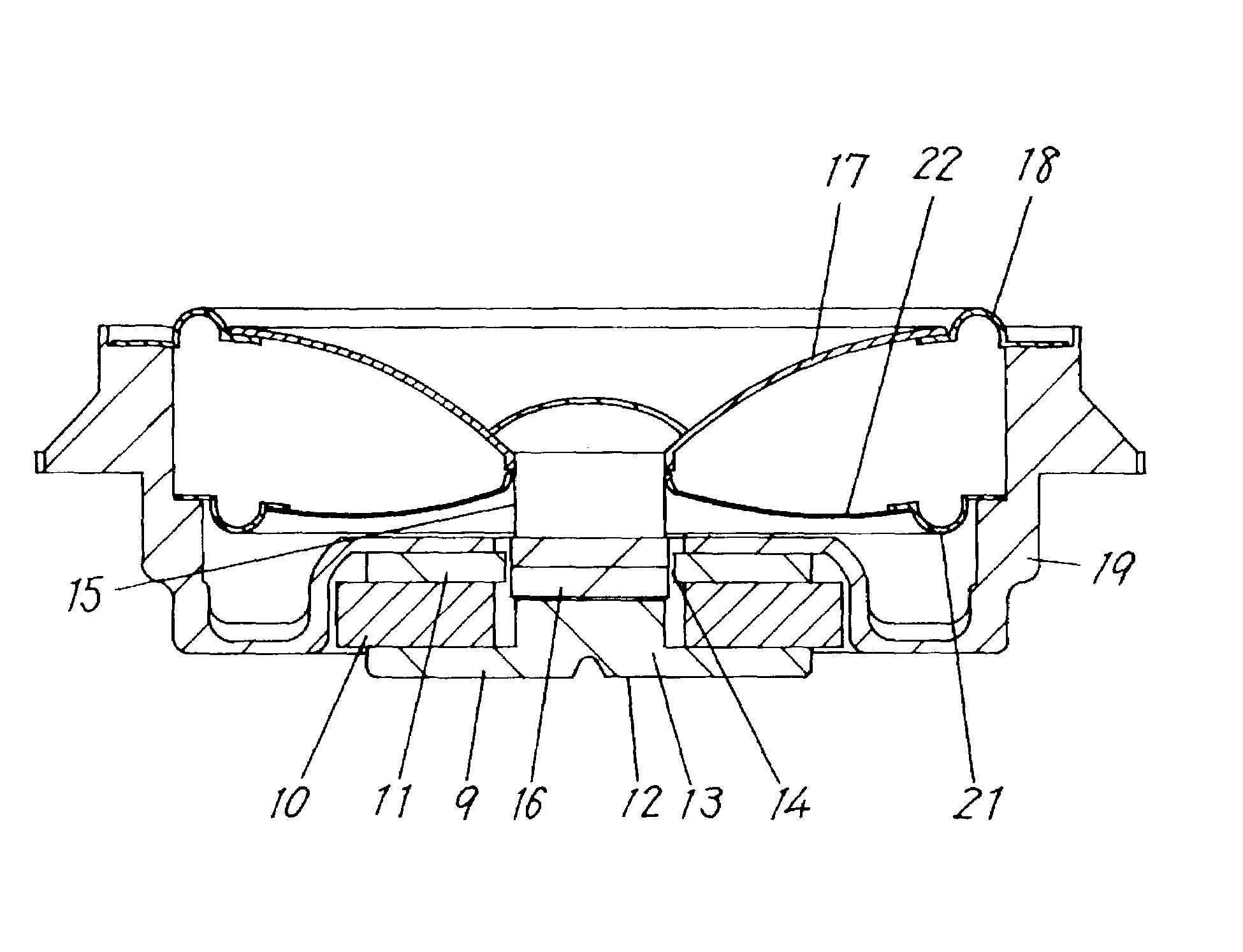
[0043]In FIG. 4, an inner peripheral part of a substantially cone shape suspension holder 22 is linked with the voice coil member 15 at a linked position which is closer to the magnetic circuit 9 than a linked position of the diaphragm 17 and the voice coil member 15. The suspension holder 22 and the diaphragm 17 are substantially symmetrical with analog each other about a median of the suspension holder 22 and the diaphragm 17. As a result, a long distance between a fulcrum of the first edge 18 and a fulcrum of the second edge 21 can be obtained, thereby preventing the voice coil member 15 from rolling.

third exemplary embodiment

[0044]The third exemplary embodiment is demonstrated hereinafter with reference to FIG. 5. FIG. 5 is a sectional view of a loudspeaker in accordance with the third exemplary embodiment of the present invention. The same constituent elements as in the first and the second exemplary embodiments are identified with the same reference numbers.

[0045]In FIG. 5, an inner peripheral part of the suspension holder 23 is linked with the voice coil member 15 at a linked position which is closer to the magnetic circuit 9 than a linked position of the diaphragm 17 and the voice coil member 15. An outer peripheral part of the suspension holder 23 is bent downward. As a result, a distance between a fulcrum of the first edge 18 and a fulcrum of the second edge 21 is expanded maximally, thereby preventing the voice coil member 15 from rolling.


PUM


Abstract

A high efficiency loudspeaker without a damper is provided. The loudspeaker includes magnetic circuit having a magnetic gap and a voice coil member, which has movable coil, disposed in the magnetic gap of the magnetic circuit. The loudspeaker also includes a diaphragm, whose inner peripheral part is linked with the voice coil member, outside the magnetic gap and a frame linked with an outer peripheral part of the diaphragm via a first edge. An inner peripheral part of a suspension holder is linked with the voice coil member at a linked position which is closer to the magnetic circuit than a linked position of the diaphragm and the voice coil member. An outer peripheral part of the suspension holder is linked with a frame via a second edge. The first edge and the second edge are substantially symmetrical with each other about a median of a first edge and a second edge.

Description

TECHNICAL FIELD[0001]The present invention relates to a loudspeaker.BACKGROUND ART[0002]As shown in FIG. 22, a structure of a conventional loudspeaker includes a magnetic circuit 1, voice coil member 4, diaphragm 5 and frame 7. The voice coil member 4, which has movable coil 3, is disposed in a magnetic gap 2 of the magnetic circuit 1. An inner peripheral part of the diaphragm 5 is linked with the voice coil member 4 outside the magnetic gap 2. An outer peripheral part of the diaphragm 5 is linked with the frame 7 via an edge 6. An electric signal, which is supplied from an audio amplifier and the like, is input to the coil 3 of the voice coil member 4, and the voice coil member 4 is then excited. As a result, force is transmitted to the diaphragm 5, and then the diaphragm 5 vibrates air, thereby changing the electric signal into sound.[0003]As shown in FIG. 22, an inner peripheral part of a damper 8 is fixed between the coil 3 of the voice coil member 4 and a fixed point of the inn...

Claims


Application Information

Patent Timeline
Patent Type & Authority Patents(United States)
IPC IPC(8): H04R25/00H04R7/12H04R7/16H04R9/04H04R9/06
CPCH04R9/043H04R9/02
Inventor FUNAHASHI, OSAMUMORIMOTO, HIROYUKIOKAMOTO, YUKIO
Owner PANASONIC CORP
Why Eureka
Try Eureka