Force sensor assembly

a technology of force sensor and assembly, which is applied in the direction of force/torque/work measurement apparatus, screws, instruments, etc., can solve the problems of affecting the accuracy of force sensor, affecting introducing more complex operation for tightening nuts, so as to reduce the accuracy of force measurement, facilitate the movement of force sensors, and facilitate the positioning of force sensors

Inactive Publication Date: 2007-05-01
HONDA MOTOR CO LTD
View PDF12 Cites 57 Cited by
  • Summary
  • Abstract
  • Description
  • Claims
  • Application Information

AI Technical Summary

Benefits of technology

[0011]Taking into account drawbacks associated with the conventional technique, the present invention seeks to provide a force sensor assembly which is able to prevent a decrease in accuracy of force measurement due to a displacement and an error which may occur while a force sensor is mounted.
[0013]When the nut and spacer are tightened onto the threaded portion with the predetermined fastening torque, the spacer deforms in its thickness direction. When the nut has struck the restricting member to cease rotation, the spacer does not deform any more. Because it is possible to provide stable control for fastening the nut, the nut will not be excessively tightened onto the threaded portion. As a result, it is possible to increase detection accuracy, because chances that axial and radial forces excessively act on the force sensor are eliminated. Furthermore, because it is possible to exert relatively high torque on the nut, the force sensor can be securely attached to the first support member.
[0015]The invention described above provides an easier movement of the force sensor when its adjustment of location is carried out, thereby allowing an easier positioning of the force sensor.
[0016]Furthermore, the present invention is able to prevent a decrease in accuracy for force measurement, which is caused by a displacement and error while the force sensor is mounted.

Problems solved by technology

The technique described above, which requires a mechanism that allows the seat cushion frame to pivot relative to the upper rail, inevitably renders the assembly complex.
However, because the force sensor assembly disclosed in the patent document 2 requires that tightening of a nut onto the threaded portion does not have an adverse effect on the force sensor, it will be necessary to introduce more complex operation for tightening the nut.
If an excessive torque is imposed on the nut, for example, it will affect adversely the force sensor to provide less accuracy due to a tensile stress axially acting on the threaded portion.
In addition, because an origin of the force sensor is shifted, an available range for detecting a force will be narrowed, which leads to difficulty in implementing highly accurate detection.
There is also another problem that decreases accuracy for detection.
It may be that the excessive torque induces torsion about an axis of the force sensor.
On the other hand, when tightening is carried out paying attention to an effect on the force sensor, it may possibly occur that the torque falls short to create looseness between the seat cushion frame and the upper rail, which is a cause for incomplete fastening.
A force sensor assembly disclosed in the patent document 1, which is secured to a seat frame and a sliding frame, tends to suffer preload when it is mounted.
There are several causes for this preload, such as an error in parallelism of the sliding frame, variation in dimensions for a sensor mounting area of the seat frame which is created during its fabrication and a displacement of mounting position of a seat onto a vehicle body.
In this case, distortion caused by the preload in the force sensor may add up to a false detection including the distortion in addition to the true weight of a passenger, or may create a measurement error due to deterioration of accuracy of the force sensor.

Method used


Image

  • Force sensor assembly
  • Force sensor assembly
  • Force sensor assembly

Examples


first embodiment

a. First Embodiment

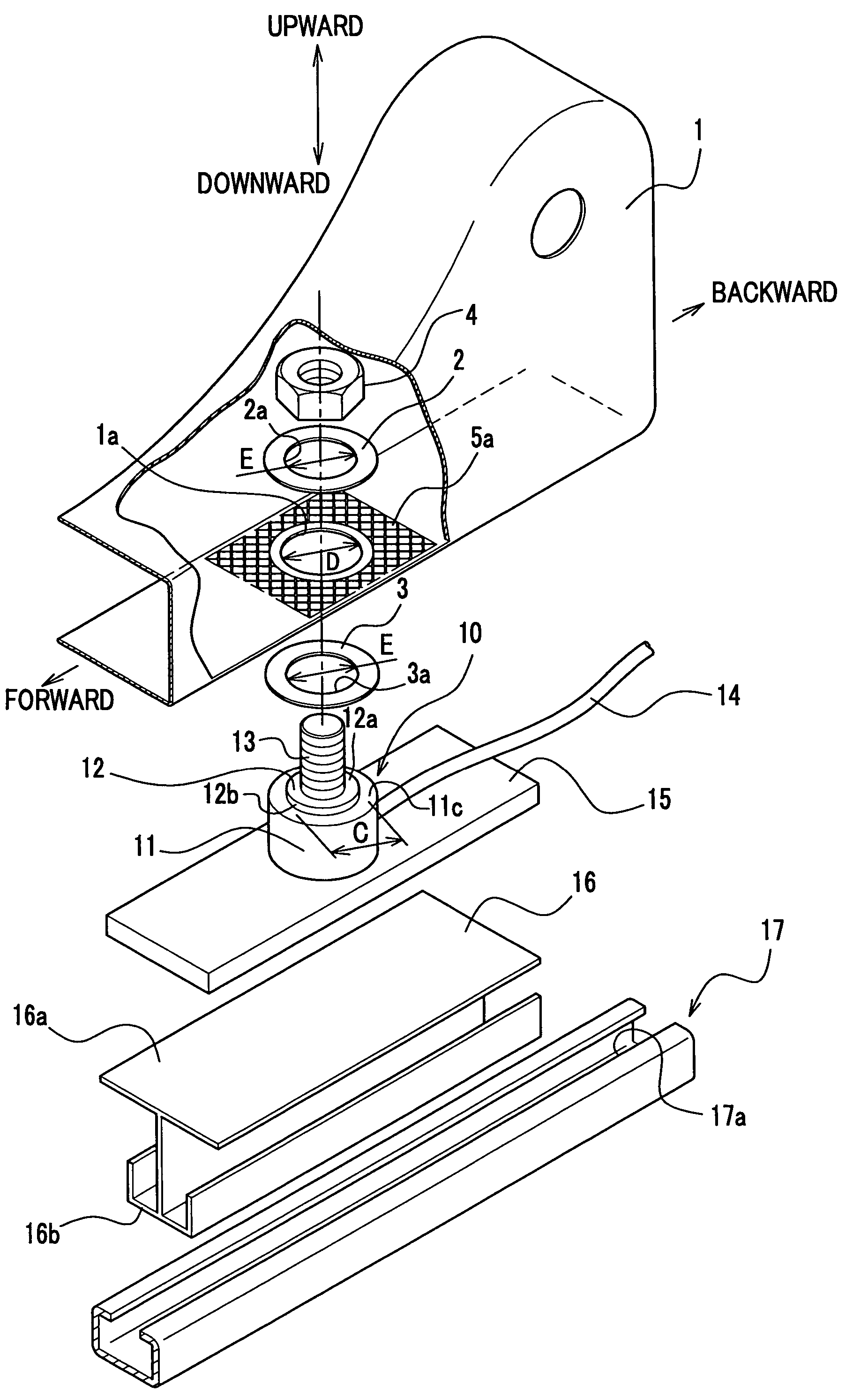
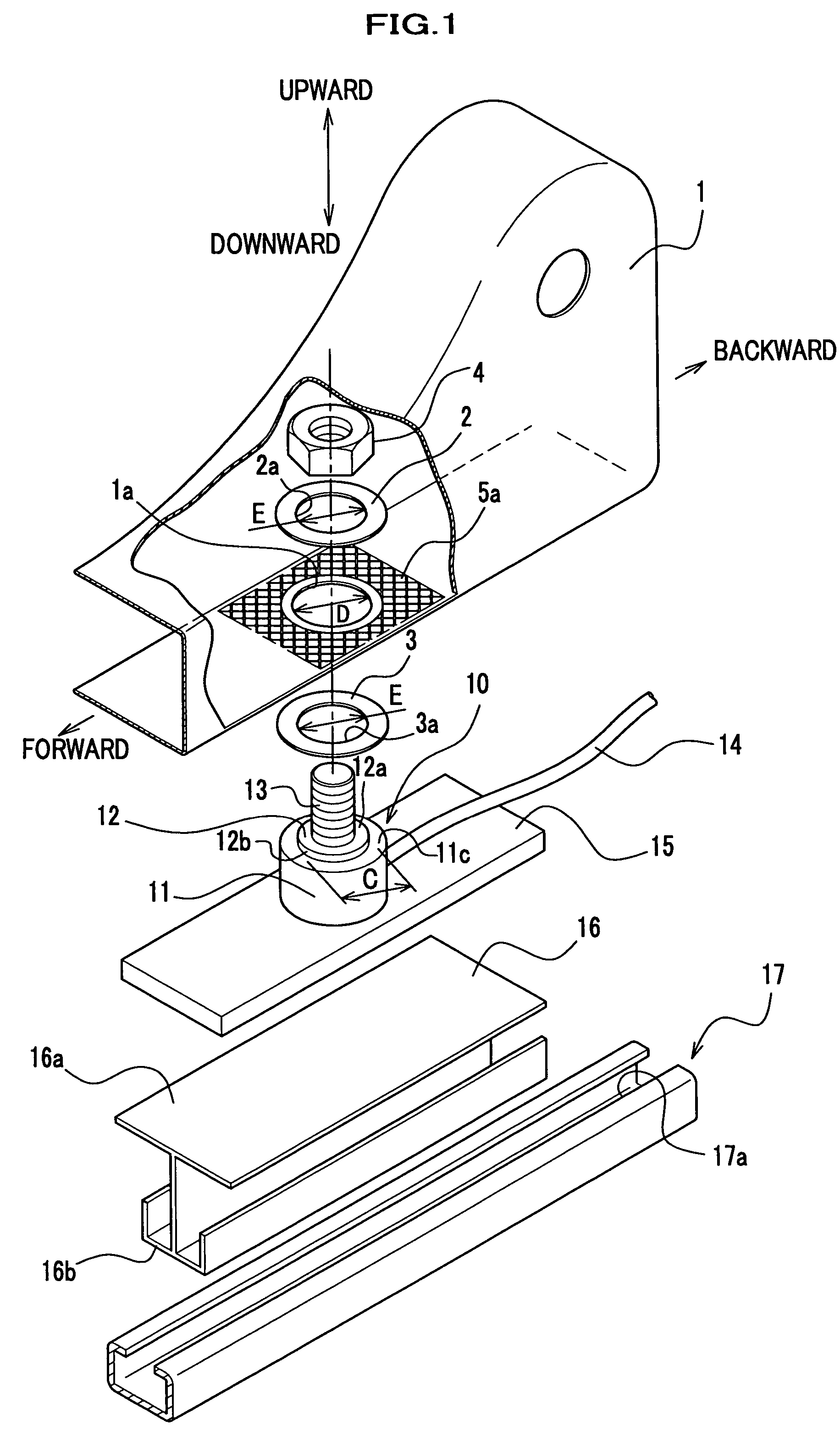
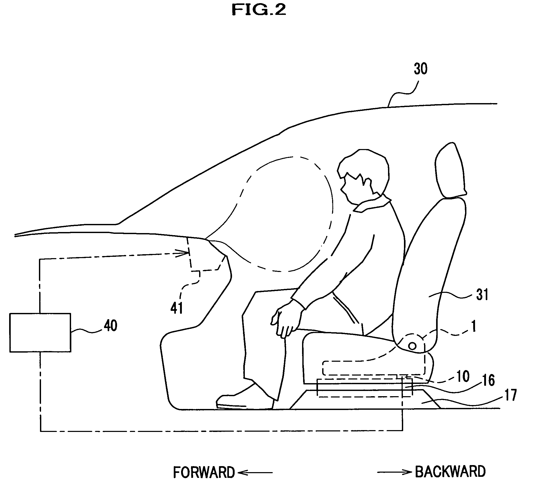
[0035]As shown in FIG. 2, a force sensor assembly according to a first embodiment of the present invention is, for example, applied to a side seat 31 of a vehicle 30. The side seat 31 includes a seat frame 1 (a first support member) and a sliding frame 16. A force sensor 10 is interposed between the seat frame 1 and the sliding frame 16. A force which is detected by the force sensor 10 is transmitted to a control unit 40 as an electrical signal, which is used for controlling inflation of an air bag 41 by the control unit 40.

[0036]As shown in FIG. 1, the sliding frame 16 includes integrally formed two portions, a flange 16a and a sliding portion 16b. The flange 16a, which is shaped like a plate, supports a bracket 15. The sliding portion 16b, which has a substantially T-like shape, is supported by a seat rail 17, which is secured to a floor in a cabin. The seat rail 17 has a guide portion 17a running in forward and backward directions, in which a lower portion of t...

second embodiment

b. Second Embodiment

[0056]Description is given of a second embodiment of the present invention with reference to the accompanying drawings.

[0057]As shown in FIG. 8, force sensors 110 and a control unit 140 are disposed in a seat 131. When a passenger is seated on the seat 131, four pieces of the force sensors 110, which are mounted between a seat frame 101 and a sliding frame 116 in forward, backward, right and left directions, detect a force acting on the seat 131, which undergoes processing carried out by the control unit 140.

[0058]A signal of force detected by a force sensor 110 is used for an air bag device and a seat belt retractor (both not shown) provided for a side seat. The control unit 140 determines whether the passenger seated on the seat 131 is an adult, a child or an infant based on the signal, providing appropriate inflation of an airbag and pretension of a seat belt according to the passenger.

[0059]The control unit 140 including a CPU and ROM is mounted on the seat f...

third embodiment

c. Third Embodiment

[0103]A force sensor is not necessarily mounted between a seat frame and a sliding frame. It may be alternatively possible that the force sensor is placed between a member, which receives a force including a passenger and a seat, and a lower structural member disposed under a cushion of the seat. For example, it may be possible to place the force sensor between the seat and a floor panel (see FIG. 15).

[0104]A lower structural member disposed under a cushion of a seat, which is placed under a seat cushion 131a, is comparable to a seat frame 101, a sliding frame 116, a seat rail 117 as shown in FIG. 8, or a seat frame 201, a seat rail 217, a rail support member 212, a base frame 213 a seat bracket 214 and a floor panel 215 as shown in FIGS. 15 and 16.

[0105]As shown in FIGS. 15 and 16, a bracket 115 of a force sensor 110 is secured to the base frame 213, which is secured to the seat bracket 214 of the floor panel 215. A nut 104 is tightened onto a threaded portion 11...


PUM


Abstract

A force sensor assembly includes a force sensor, a first support member, a threaded portion, an opening made in the first support member, a nut, a restricting member and a spacer. The nut is screwed onto the threaded portion which is inserted through the opening. The restricting member is provided between the force sensor and the nut. The spacer, which is provided between the force sensor and the nut, is deformable in a direction of its thickness. The shape of the spacer is adapted to avoid interference with the restricting member. Before the nut is tightened onto the threaded portion, a summation of thickness for the first support member and the spacer is adapted to be not less than a height of the restricting member. The nut is tightened up with a predetermined fastening torque until the spacer deforms so that the nut strikes the restricting member.

Description

BACKGROUND OF THE INVENTION[0001]The present invention relates to a force sensor assembly, and more particularly relates to a force sensor assembly, which is able to provide accurate measurement of a force.[0002]An air bag system is mounted on a vehicle so as to provide safety for a passenger in case of a collision. A sensor is installed in a side seat in order to control the air bag system. A force sensor is typically selected for this sensor, which is able to measure the weight of a passenger when he is seated on the seat. This force sensor, which detects a seated passenger, generates a signal for controlling inflation of the air bag system. The control includes a case where a system prevents an air bag from inflating if the system determines that a passenger is a child, and another case where a system adjusts speed of inflation of an air bag according to the weight of a passenger, for example.[0003]Patent document 1 discloses a technique associated with a force sensor assembly. T...

Claims


Application Information

Patent Timeline
Patent Type & Authority Patents(United States)
IPC IPC(8): F16B31/02
CPCB60N2/002G01G19/4142
Inventor YAMAZAKI, TATSUYA
Owner HONDA MOTOR CO LTD
Why Eureka
Try Eureka