Optical subassembly with a heat-radiating fin and an optical transceiver installing the same

a technology of optical subassembly and heat-radiating fin, which is applied in the direction of semiconductor lasers, semiconductor/solid-state device details, instruments, etc., can solve the problems of enhancing the heat dissipation of semiconductor devices, and achieve the effects of facilitating the positioning between the subassembly and the heat-radiating fin, wide area, and enhanced heat dissipation

a technology of optical subassembly and heat-radiating fin, which is applied in the direction of semiconductor lasers, semiconductor/solid-state device details, instruments, etc., can solve the problems of enhancing the heat dissipation of semiconductor devices, and achieve the effects of facilitating the positioning between the subassembly and the heat-radiating fin, wide area, and enhanced heat dissipation

US7210862B2Active Publication Date: 2007-05-01SUMITOMO ELECTRIC IND LTD

Image

  • Optical subassembly with a heat-radiating fin and an optical transceiver installing the same
  • Optical subassembly with a heat-radiating fin and an optical transceiver installing the same
  • Optical subassembly with a heat-radiating fin and an optical transceiver installing the same

Examples


first embodiment

[0020

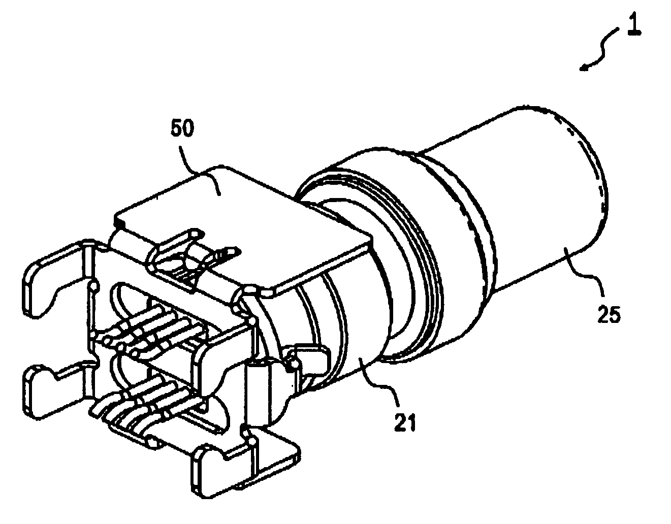
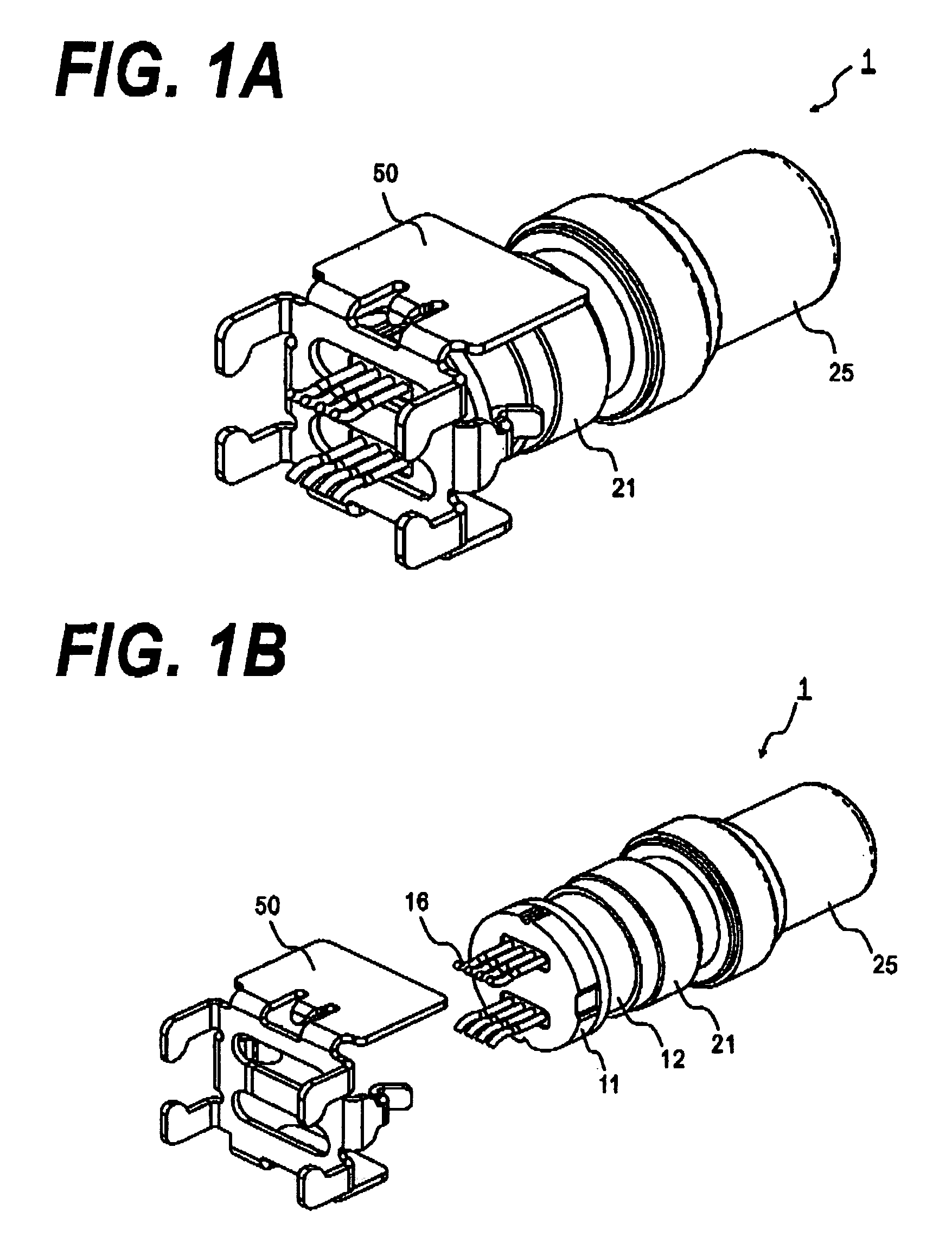
[0021]Next, preferred embodiments of the present invention will be described as referring to accompanying drawings. FIG. 1A is a perspective view of an OSA with a heat-radiating fin, and FIG. 1B is an exploded view of the OSA according to the present invention. Next, the OSA, and the radiating fin will be described in detail.

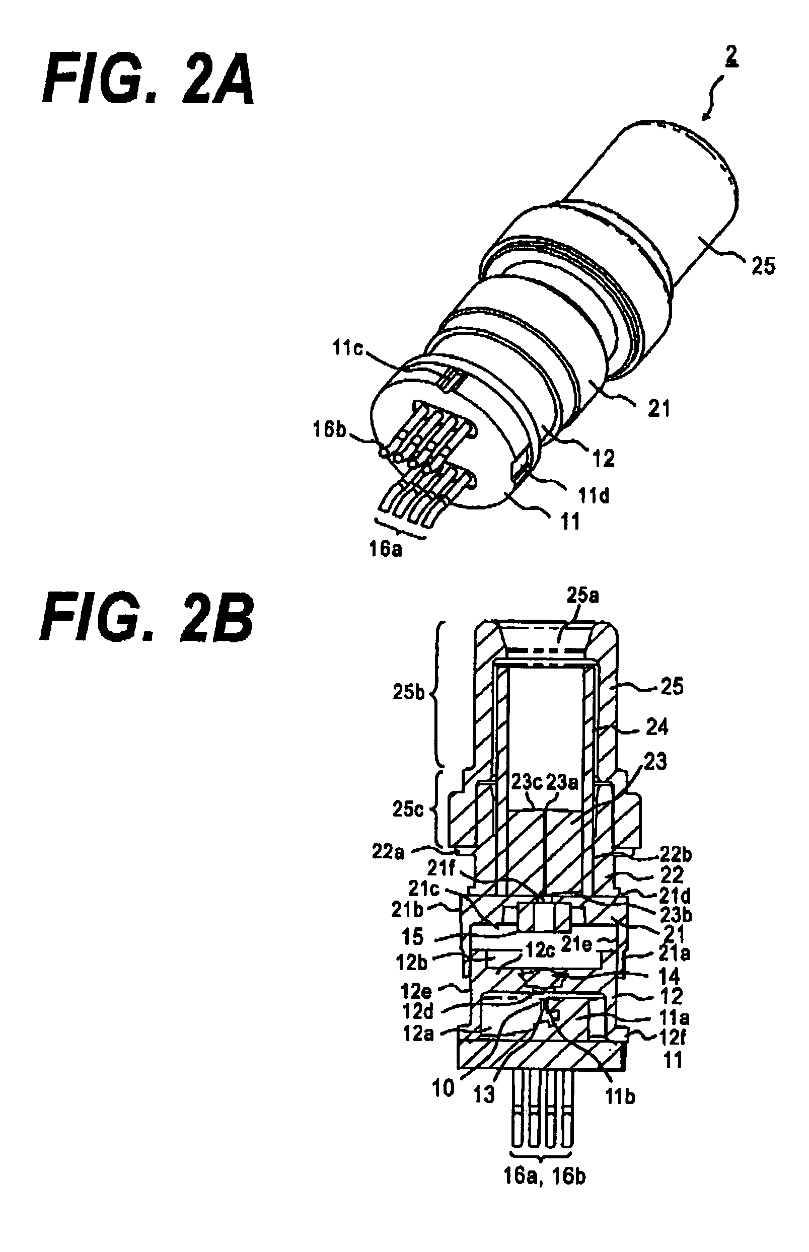
[0022]FIG. 2A is a perspective view of the OSA, and FIG. 2B is a cross sectional view of the OSA. The OSA assembles several tubular members, namely, the OSA having a co-axial package, includes a stem 11 with a disk shape, a cap 12, an alignment member 21, a bush 22, a stub 23, a sleeve 24, and a sleeve cover 25.

[0023]The stem 11 is made of, for example iron coated with nickel or coated with nickel and gold. A plurality of grooves, 11b and 11c, extending along the center axis of the cylindrical members is provided in a side of the stem 11. The groove 11c, as described later, is provided for positioning the heat-radiating fin 50, while the other groove 11b, w...

second embodiment

[0046

[0047]FIG. 5A and FIG. 5B are exploded view showing an optical transceiver that installs the OSA 2 according to the present invention. FIG. 5A is a view shown from the front-up side, while FIG. 5B is a view from a rear-bottom side. This transceiver has a configuration following the so-called GBIC (Giga-Bit Interface Converter) standard.

[0048]The optical transceiver 100 comprises a lower cover 101, a frame 102, two OSAs (the TOSA 111 and the ROSA 112), an OSA holder 103, and an upper cover 104. The frame 102 provides a receptacle 121 having two openings in the front side. The head portion of the TOSA 111 and the ROSA 112 are protruded within the opening of the receptacle 121, thus, within the receptacle, optically coupling between the ferrule included in the optical connector that is to be mated with the receptacle and the two OSAs are realized. The OSA holder 103 and the frame 102 define the positions of two OSAs, 111 and 112, in the frame by sandwiching them. The front wall of...


PUM


Abstract

The present invention provides a configuration to improve a heat-radiating effect of an optical subassembly having a co-axial package and a plurality of lead pins arranged in an arrayed shape. The heat generated inside the subassembly may be dissipated through the heat-radiating fin attached to a flat surface, not a curved side surface of the subassembly such that the lead pins provided in the subassembly pass through the slot provided in the heat-radiating fin. The heat-radiating fin has a slab portion attached to the cover of the transceiver, when the subassembly is installed within the transceiver. Thus, the heat generated in the subassembly can be easily and effectively dissipated to the cover.

Description

CROSS REFERENCE TO RELATED APPLICATIONS[0001]This application claims the benefit of prior filed U.S. Provisional Application 60 / 579,969 filed on Jun. 16, 2004 entitled “An optical sub-assembly with a radiating fin and an optical transceiver installing the same” by inventors Yoshikawa; S., and Mizue; T., which is incorporated herein by reference in its entirety.BACKGROUND OF THE INVENTION[0002]1. Field of the Invention[0003]The present invention relates to an optical assembly (hereinafter denoted as OSA), in particular, to configuration for heat dissipation thereof that installs a device generating a large heat.[0004]2. Related Prior Art[0005]The OSA installs an optical semiconductor device therein. A semiconductor laser diode and a semiconductor photodiode are well known as the optical semiconductor device. The OSA installing the laser diode is called as a transmitting optical sub-assembly (TOSA), while the OSA installing the photodiode is called as a receiving optical sub-assembly ...

Claims


Application Information

Patent Timeline
01 May 2007
Publication
US7210862B2
IPC
G02B6/255; G02B6/42; H01L23/40; H01S3/04; H01S5/024
CPC
H01L23/4093; H01S5/024; G02B6/4269; G02B6/4292; H01L2924/0002; H01L2924/00
Inventors
YOSHIKAWA, SATOSHI; MIZUE, TOSHIO