Entrapment snare for the termination of vehicle pursuits

a technology of vehicle pursuit and entrapment snare, which is applied in the direction of roadway safety arrangements, roads, construction, etc., can solve the problems of high-speed vehicle pursuit, injuring and killing many innocent people, and currently facing law enforcement, so as to reduce the rotational radius

Active Publication Date: 2007-05-01
GOODMAN MICHAEL C
View PDF49 Cites 32 Cited by
  • Summary
  • Abstract
  • Description
  • Claims
  • Application Information

AI Technical Summary

Benefits of technology

[0018]As the weights rotate toward each other, the radius of rotation decreases because the free ends of the cable are getting shorter as the cable wraps around the tire. As the radius of rotation decreases, conservation of angular momentum causes the speed of rotation of the two projectile weights to increase. Thus, very quickly, the two ends of the cable attached to the projectile weights will pull tightly into place in front of the target tire.
[0019]Thus, the goal of getting some sharp spikes from behind the tire to in front of the tire has been accomplished. If the tire is in forward motion, it will roll over those parts of the spike cable that cross around in front of the tire. If there are spikes, hooked barbs or fishing tackle attached at closely spaced intervals to the cable, the target tire will run over some of those sharp objects. The design can be such that the tire is immediately punctured but an alternative design calls for embedding smaller spikes in the tire, securing the cable to the tire. If there is a mesh arrangement of other spike cables (a cable ladder) attached to, and trailing behind, the forward most spike cable, that arrangement will be drawn into, and wrap around the target tire like a snow chain. Various types of spikes or barbs can deflate the tire rapidly or slowly.
[0021]All versions of the present invention attack a rear tire only, leaving the front tires free to continue their normal steering function. Thus, the chance of the suspect vehicle losing control before being brought to a stop is minimized.

Problems solved by technology

One of the most difficult problems currently facing law enforcement is the issue of high-speed vehicle pursuits.
High-speed pursuits injure and kill many innocent people every year and some police departments no longer chase fleeing vehicles.
The problem with a no-pursuit policy is that criminals become more brazen in their activities, confident that the police will not chase them if they are in a motor vehicle.
Because the front of a vehicle is usually heavier than the back because of the weight of the engine, it is sometimes possible to shove the rear of a fleeing vehicle sideways, causing it to lose control and go into a spin while the police vehicle stays in control.
This technique is quite dangerous, involving vehicle-to-vehicle contact at high speeds.
In the process of pushing the suspect, the police vehicle could also go out of control and will experience collision damage during the aggressive contact.
Thus, police vehicle, suspect vehicle or both could go out of control, endangering everybody on the road.
This causes the police vehicle to become vulnerable to the suspect's actions, which could force both vehicles into a crash.
Another weakness of the pursuit intervention technique is that it does not actually disable the fleeing vehicle but merely throws it into a spin.
Thus, spike strips can only be used when officers are at a position where the suspect is going to pass by and no other vehicles are going to pass by.
Thus, there is the possibility that a suspect vehicle could lose control and crash into another vehicle or a pedestrian.
If the suspect vehicle is going too fast to stop before hitting the barricades, the suspect could be killed, making this a potentially deadly use of force.
If such a device deploys late, it will blow out the front tires.
If it rotates during its travel, it might deploy perpendicular to the tire axles and do nothing at all.
If such a device deploys early, it will bounce against the back of the rear tires, probably getting kicked away.
Experiments have shown that when both tires are attacked at the same time with devices that are linked together, the connecting cable will slam into the bottom of the fleeing vehicle's gas tank.
Such a technique would only work on cars with electronic ignition, the pulse destroying at least some electronic components.
An energy level high enough to do this would threaten the health of anyone inside or near the targeted vehicle.
It would kill someone with a pacemaker, even if they were in another vehicle nearby or on a sidewalk.
Such an energy discharge could possibly cause a vehicle gas tank to explode (on the suspect vehicle or any other vehicle nearby).
Tires are small, hard targets to hit, and bullets that miss could hit an innocent bystander or a vehicle gas tank.
One problem with any of these designs is that they will not work on a vehicle that is not equipped with the appropriate electronic devices.
Another problem is that criminals could disable such devices.
In the laser halting system, a piece of black masking tape covering the optical sensor on the back of the suspect vehicle would render that system inoperative.
To work, this design would require a large quantity of gas.
A small amount of gas might cause the engine to stall momentarily but it would restart after the car had rolled out of the gassed area.
If enough gas can be released to make this technique work, anyone within the affected area (drivers, passengers or pedestrians) will face a lethal threat.
The technique does nothing to control or stop the fleeing vehicle.

Method used


Image

  • Entrapment snare for the termination of vehicle pursuits
  • Entrapment snare for the termination of vehicle pursuits
  • Entrapment snare for the termination of vehicle pursuits

Examples


Embodiment Construction

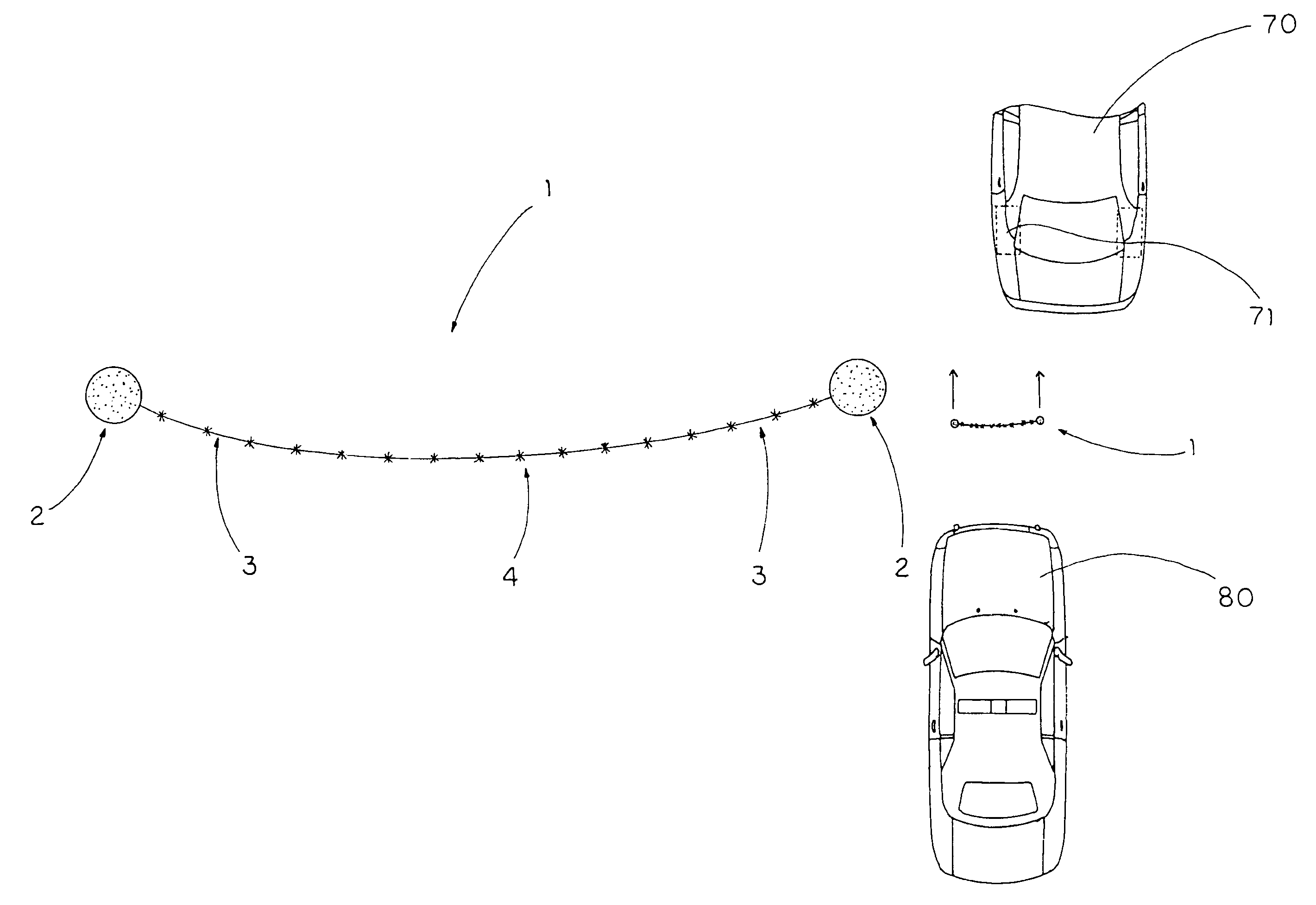
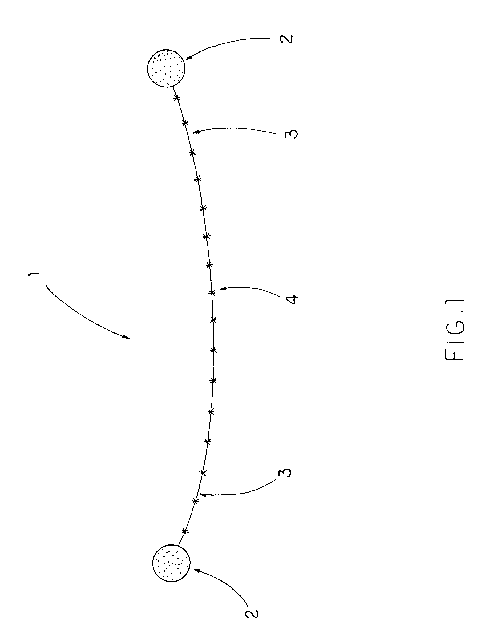
[0038]FIG. 1 shows an entrapment snare 1 consisting of a flexible cable 3 with projectile weights 2 attached to each end of cable 3. Hooked barbs 4 such as fishing tackle are attached to cable 3 at intervals along said cable.

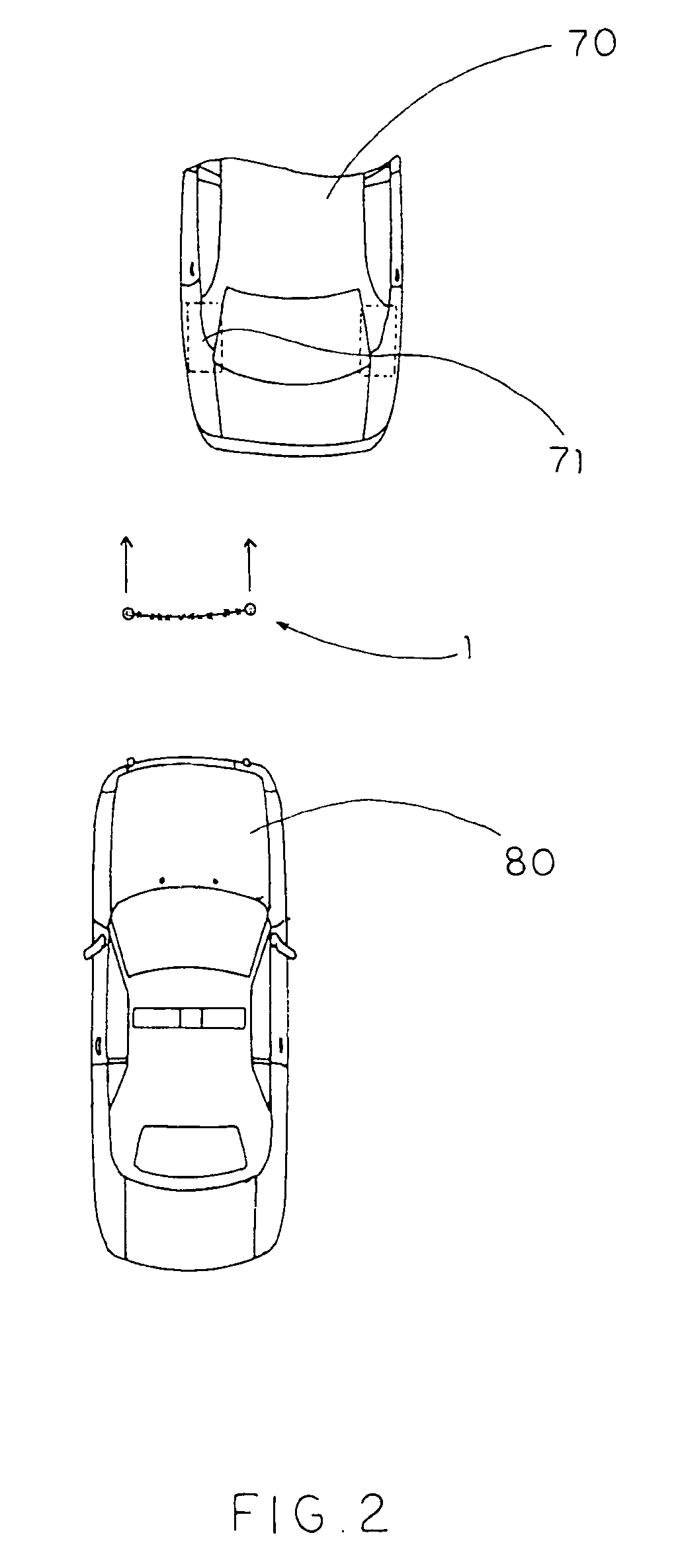
[0039]FIG. 2 shows the entrapment snare 1 after it has been launched from a police vehicle 80 toward a fleeing suspect vehicle 70. In FIG. 2, the left rear tire 71 of fleeing suspect vehicle 70 has been targeted by the police vehicle 80. FIG. 3 shows the entrapment snare 1 after it has been launched by projection means 100 from the police vehicle 80. As can be seen, entrapment snare 1 is traveling on or very near the surface of the ground as it heads toward the targeted tire 71 of the fleeing vehicle 70. The projectile weights 2 (shown in FIG. 1) have been forcefully projected horizontally (at ground level) in a forward direction at one of the rear tires 71 of the fleeing vehicle 70 such that the weights 2 bracket the tire 71, one weight 2 going to the left of t...


PUM


Abstract

An entrapment snare, consisting of two small but heavy weights connected by a flexible cable covered with spikes, is designed to be launched from a pursuing law enforcement vehicle at one of the rear tires of a fleeing vehicle. One heavy weight is attached to each end of the flexible cable. The weights are forcefully projected, at ground level, in a forward direction at one of the rear tires of the fleeing vehicle such that the weights bracket the tire. Initially, the two projectile weights have forward linear momentum and the cable connecting them is slack. The middle of the cable hits the target tire at or near where the rubber meets the road and the cable goes into tension. Very quickly, the two ends of the cable attached to the projectile weights pull tightly into place in front of the target tire.

Description

BACKGROUND OF THE PRESENT INVENTION[0001]1. Field of the Invention[0002]This invention relates to vehicle disabling devices used by law enforcement vehicles to stop fleeing suspect vehicles. More particularly, this invention relates to a vehicle-disabling device that can be projected from a police vehicle toward a rear tire of a fleeing vehicle, said device flattening the tire of the fleeing vehicle.[0003]2. Description of the Related Art[0004]One of the most difficult problems currently facing law enforcement is the issue of high-speed vehicle pursuits. Once a police vehicle activates its forward facing red light and sounds its siren, any vehicle in front of the police vehicle is required by law to pull over to the right side of the road and stop. When a suspect vehicle fails to do this, police are faced with the choice of going into pursuit or letting the suspect go. Neither alternative is a good one. High-speed pursuits injure and kill many innocent people every year and some pol...

Claims


Application Information

Patent Timeline
Patent Type & Authority Patents(United States)
IPC IPC(8): E01F13/12
CPCE01F13/12F41H13/00
Inventor CHRISTLE, YA-MAYGOODMAN, MICHAEL C.
Owner GOODMAN MICHAEL C
Why Eureka
Try Eureka