Powder compacting apparatus

a technology of compacting apparatus and powder, which is applied in the direction of dough shaping, manufacturing tools, applications, etc., can solve the problems of inconvenient and time-consuming work, difficult to precisely align the upper punch, and difficult to fix the upper holder 112/b>, etc., to save labor time and facilitate the mounting and dismounting of dies in the present apparatus.

Inactive Publication Date: 2007-05-01
JAPAN ATOMIC ENERGY AGENCY INDEPENDANT ADMINISTRATIVE CORP
View PDF2 Cites 1 Cited by
  • Summary
  • Abstract
  • Description
  • Claims
  • Application Information

AI Technical Summary

Benefits of technology

[0014]The mounting and dismounting of dies in the present apparatus are much easier and much quicker than in the prior art apparatuses, thus saving labor time. Particularly, the upper punches can be aligned with the dies more smoothly in situ, without moving a set of the dies and relevant members to or away from any mold changer.

Problems solved by technology

Thus, very intricate and time-consuming works are necessary when mounting and dismounting the die 121.
Due to almost impossible visual inspection of the positions of those bolts and bolt holes receiving them, the upper holder 112 is not easy to fix.
In this case, it will however be more difficult to precisely align the upper punch 113 with the die 121, also failing to smoothly attach and quickly fasten those bolts.

Method used


Image

  • Powder compacting apparatus
  • Powder compacting apparatus
  • Powder compacting apparatus

Examples


Embodiment Construction

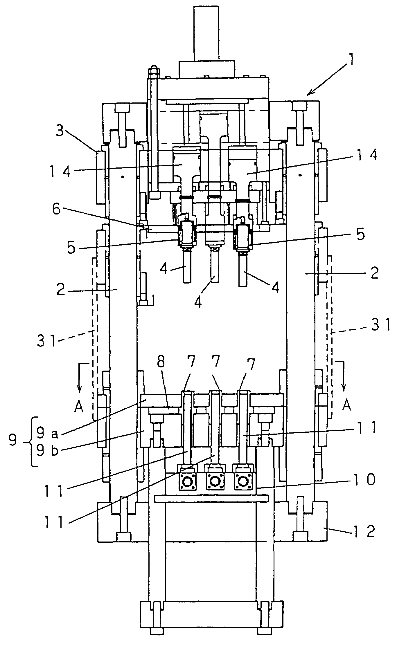
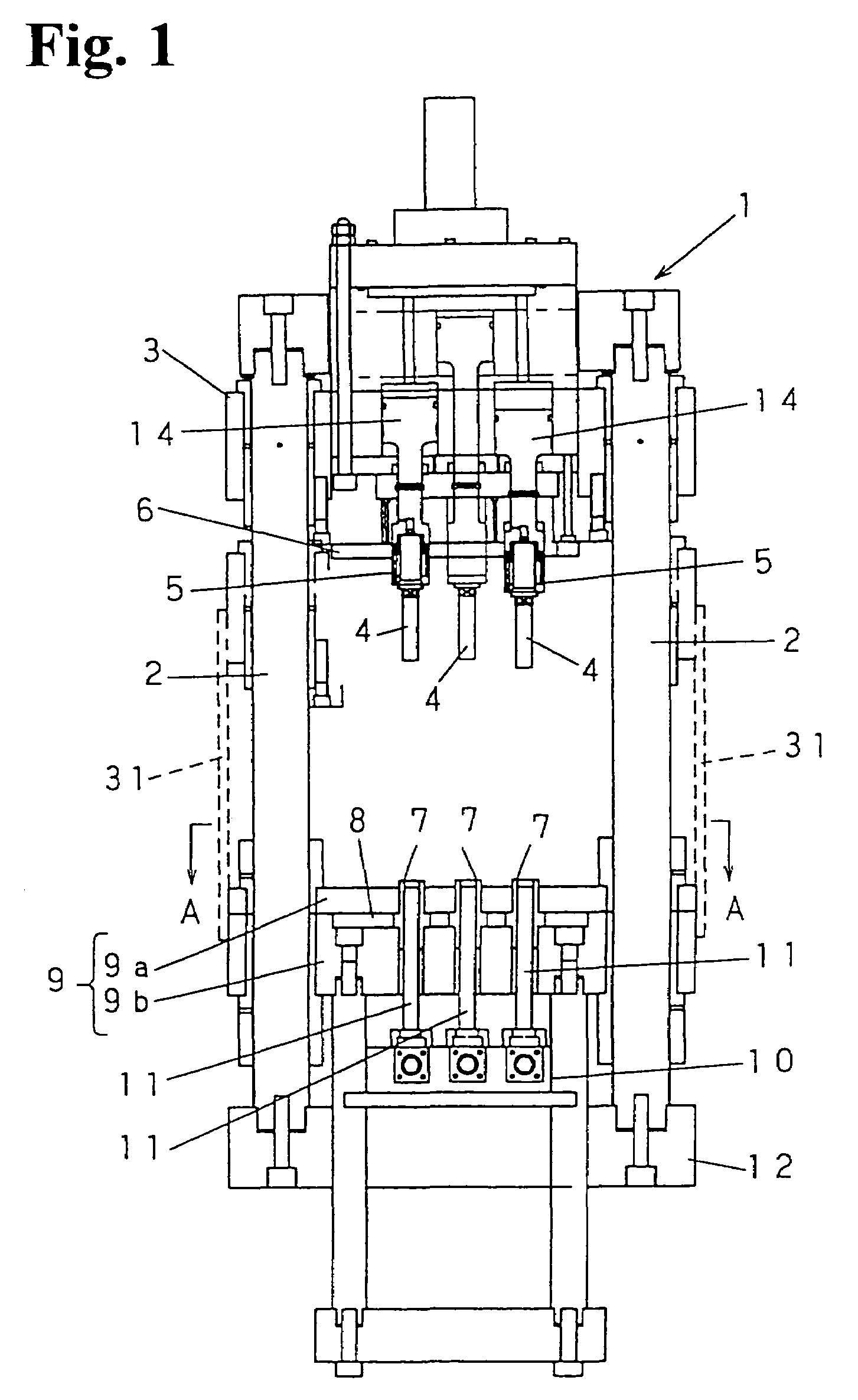
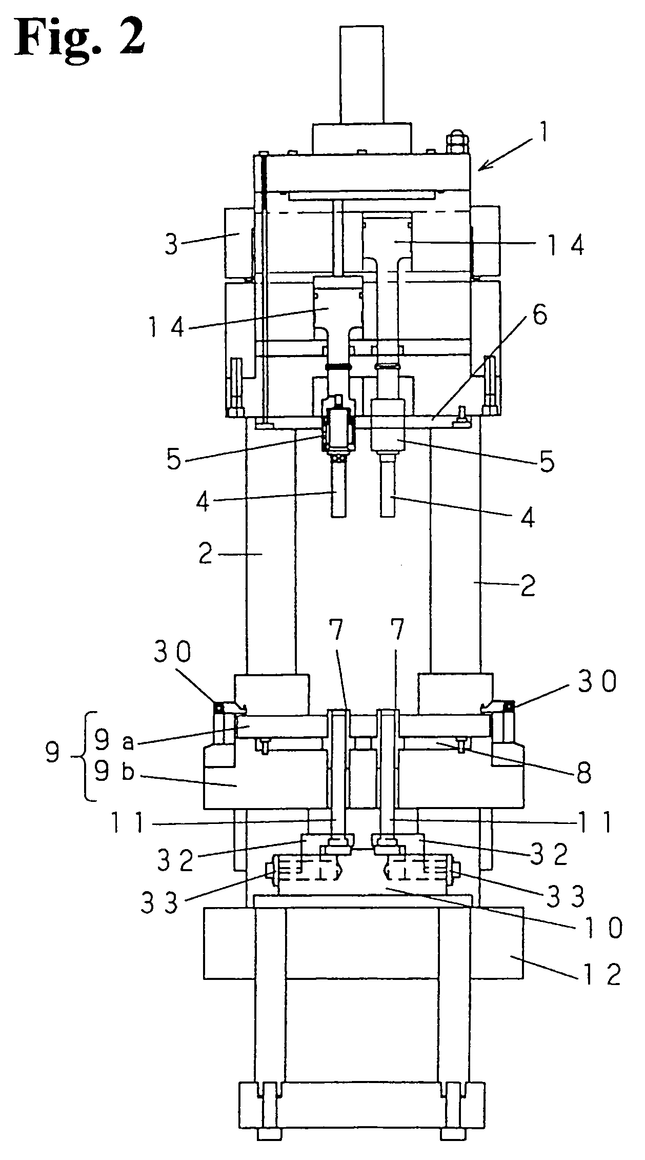
[0022]As shown in FIGS. 1 and 2, a powder compacting apparatus 1 of the present invention comprises a top plate 3, and upper punches 4 held by punch holders 5. These plate 3 and holders 5 are to be driven up and down along guide shaft 2. An upper retentive plate 6 serves to fix the punch holders 5 on the top plate 3. The apparatus further comprises dies 7 that extend vertically and centrally of a die holder 8, which in turn is locked in position by a die plate 9. In other words, such a holder 8 and die plate 9 do function to fixedly secure the dies 7. The apparatus still further comprises a bottom plate 12 that supports thereon a lower retentive plate 10 so as to hold lower punches 11 in position.

[0023]The guide shafts 2 are arranged at four corner regions of the die plate, surrounding 6 (six) dies 7 as seen in FIG. 3.

[0024]An oil-hydraulic or electric motor (not shown) will drive the top plate 3 to move up and down along the guide shafts 2 holding this plate. The top plate 3 in tur...


PUM

PropertyMeasurementUnit
compressaaaaaaaaaa
diameteraaaaaaaaaa
hydraulic pressureaaaaaaaaaa

Abstract

A powder compacting apparatus (1) has a top plate (3), a die plate (9) and a bottom plate (12), combined with each other as follows. The top plate (3) holds upper punches (4) in place by punch holders (5), and the die plate (9) firmly grips a die holder (8) holding dies (7). The bottom plate (12) keeps lower punches (11) in place gripped by clamps (32) so that an amount of powder fed into each die (7) is compacted to give a consolidated powder piece. The die plate (9) is composed of an upper part (9a) and a lower part (9b) so that the die holder (8) is sandwiched by and between the parts (9a, 9b), in such a manner that these parts cooperate with each other to secure each die (7) in position.

Description

FIELD OF THE INVENTION[0001]The present invention relates to a powder compacting apparatus for use to produce consolidated pieces of a powder.BACKGROUND OF THE INVENTION[0002]In general, powder compacting apparatuses are used for instance in the conventional metallurgy industries in which a basic iron powder is blended with a copper powder, a graphite powder or the like alloy element to prepare a composition. Usually added to this composition is a lubricant such as zinc stearate, lead stearate or the like, to provide a mixed powder that will then be compacted in a press mold. Powder metallurgy is a process for producing for example such an iron-based compacted powder pieces, and in the atomic power industries the mold is disposed in a glove box so as to produce such pieces as nuclear fuel pellets.[0003]Presses widely used in this field comprise each two or more punches for a mold.[0004]One of the prior art powder compacting apparatuses is disclosed in the Japan Patent Laying-Open Ga...

Claims


Application Information

Patent Timeline
Patent Type & Authority Patents(United States)
IPC IPC(8): B29C43/32B29C43/42B22F3/03B30B11/02B29C43/34B30B11/00B30B15/02
CPCB30B11/02B30B15/026B22F3/03
Inventor MINAKAWA, SUSUMUIWASAKI, TAKASHIIWAI, AKIRANOUNEN, KOUJISATO, MORIHIRO
Owner JAPAN ATOMIC ENERGY AGENCY INDEPENDANT ADMINISTRATIVE CORP
Why Eureka
Try Eureka