Motor cooling system

a cooling system and motor technology, applied in the direction of electric propulsion mounting, machines/engines, transportation and packaging, etc., can solve the problems of increased manufacturing cost, uneven heat radiation, and increased temperatur

Active Publication Date: 2007-05-01
HONDA MOTOR CO LTD
View PDF8 Cites 34 Cited by
  • Summary
  • Abstract
  • Description
  • Claims
  • Application Information

AI Technical Summary

Problems solved by technology

Therefore, if high-load driving such as an acceleration drive and a hill climb drive is performed in a hybrid vehicle, heat radiation is not smoothly performed in spite of a large amount of heat generated accompanying an increased load at the neutral point (that is, an increase of a consumption current) because of the high density of the strands, and a temperature rises until near an allowable limit in a comparatively short period of time.
However, in the three-phase alternating current motor of the Japanese Patent Laid-Open Publication Hei. 10-80085, because a manufacturing and the like of the winding wires and the crossover are difficult and a number of components also becomes many, manufacturing cost thereof increases and it is also difficult to ensure a reliability thereof.
In addition, even if adopting such the structure, it is actually difficult to obtain a sufficient heat resistance and radiation.
Therefore, if the hydraulic oil of the high temperature is supplied to the traction motor, the temperature of the neutral points results in rising on the contrary.

Method used


Image

  • Motor cooling system
  • Motor cooling system
  • Motor cooling system

Examples


first embodiment

[0031]Firstly will be described a configuration of a hybrid vehicle where a traction motor of a first embodiment is mounted.

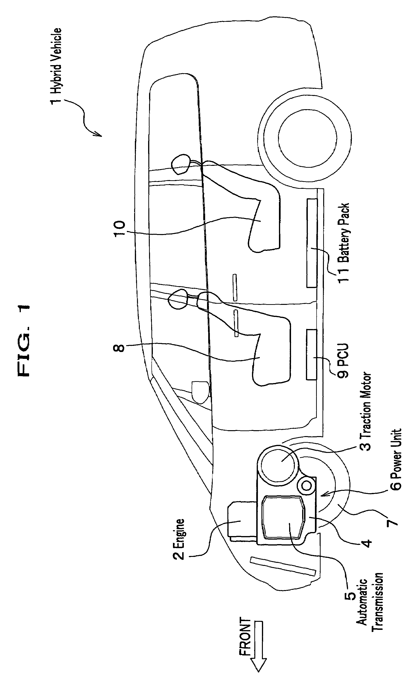
[0032]In a hybrid vehicle 1 shown in FIG. 1 an engine 2 of a driving power source (in the embodiment a four-banger gasoline engine) and a traction motor 3 configure a power unit 6 together with an automatic transmission 5 and a drive-force selector 4 that houses a differential, and are horizontally mounted on front wheels, respectively. Beneath a front seat 8 is placed a PCU (Power Control Unit) 9 comprising an inverter, a control circuit, a CPU (Central Processing Unit), and the like: the PCU 9 performs power output control of the engine 2 and the traction motor 3, drive-force distribution control for the drive-force selector 4, and the like. In addition, beneath a rear seat 10 is placed a battery pack 11 charging electric power of a high voltage (for example, 145 volts): the electric power of the battery pack 11 is supplied to the traction motor 3 through the...

second embodiment

[0044]Next will be described a second embodiment, referring to FIGS. 7 and 8.

[0045]The second embodiment adopts a configuration of directly injecting the cooling oil 41 at the neutral point 28 in an acceleration drive and a hill climb drive. In the second embodiment, because a total configuration thereof is similar to that of the first embodiment, a configuration and action thereof will be described for a different point only therefrom.

[0046]As shown in FIG. 7, although the hybrid vehicle 1 of the second embodiment adopts a configuration substantially similar to that of the first embodiment, an acceleration sensor 54 and a tilt sensor 55 are placed in a vicinity of the PCU 9 as a high-load detection mechanism. The acceleration sensor 54 and the tilt sensor 55 detect an acceleration of the hybrid vehicle 1 and a tilt of the vehicle body, and are electrically connected to the PCU 9.

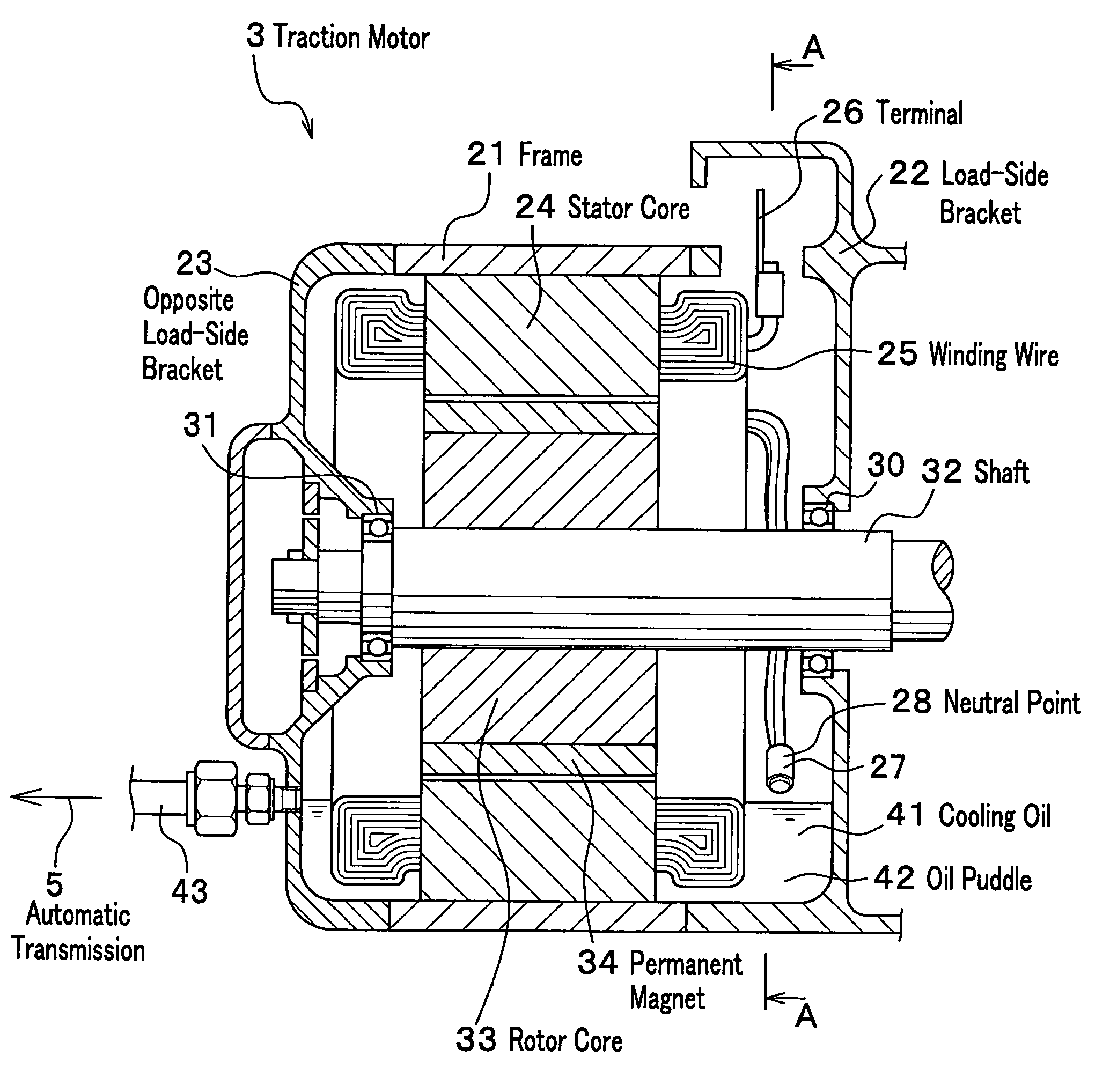
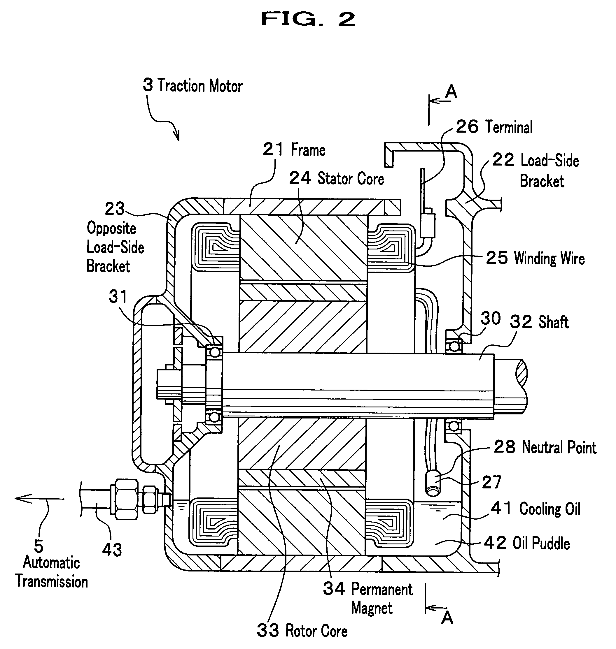
[0047]As shown in FIG. 8, in the traction motor 3 of the second embodiment the neutral point 28 is place...

third embodiment

[0054]A third embodiment adopts a configuration of directly injecting the cooling oil 41 at the neutral point 28 in a temperature rise of the traction motor 3. Also in the third embodiment, because a total configuration thereof is similar to that of the first embodiment, a configuration and action thereof will be described for a different point only therefrom.

[0055]As shown in FIG. 11, in the traction motor 3 of the third embodiment the neutral point 28 is placed upper than that of the first embodiment same as the second embodiment, and the cooling oil injection nozzle 51 is provided at an upper portion than the neutral point 28. In addition, the cooling oil injection nozzle 51 is attached in a form of penetrating through a side of the load-side bracket 22 for an axial direction of the shaft 32, and the oil connection pipe 52 is connected for supplying the ATF from a hydraulic circuit (not shown) of the automatic transmission 5.

[0056]In between the oil connection pipe 52 is equipped...


PUM


Abstract

The motor cooling system of the present invention is a system for cooling a three-phase alternating current motor mounted on a vehicle as a traction motor where oil is introduced as cooling oil from driving-related equipment of the vehicle, wherein the traction motor is equipped with a stator having a neutral point, wherein the vehicle is in a high-load driving state when a larger load is applied to the traction motor than a predetermined amount, the neutral point contacts the cooling oil with a larger contact amount than when the vehicle is not in the high-load driving state.

Description

BACKGROUND OF THE INVENTION[0001]1. Field of the Invention[0002]The present invention relates to a motor cooling system used as a traction power source of a hybrid vehicle and the like, and to a technology for effectively cooling a neutral point.[0003]2. Description of the Related Art[0004]A hybrid vehicle mounts an engine (internal combustion engine) and a traction motor as a traction power source and appropriately uses both or one of these, thereby realizing a highly efficient driving. For example, using exclusively the engine in cruising on a highway and the like, and both of the engine and the traction motor in an acceleration drive and a hill climb drive, a good fuel consumption and a high driving performance are realized. As a traction motor of the hybrid vehicle, a three-phase alternating current motor of a star-connection having a neutral point is generally used because of its high efficiency and control easiness. In this kind of a three-phase alternating current motor, beca...

Claims


Application Information

Patent Timeline
Patent Type & Authority Patents(United States)
IPC IPC(8): H02K9/19H02K9/00B60K7/00B60L50/16F01P3/00H02K9/193H02K11/00
CPCB60K6/48H02K9/19H02K9/193H02K11/0047B60K7/0007B60K2001/003B60L2240/425B60W2510/087F01P2003/006F01P2050/24F01P2060/045Y02T10/6221Y02T10/641Y02T10/642H02K11/25Y02T10/62Y02T10/64
Inventor TSUTSUI, TAKAHIRONAGI, TAKAAKI
Owner HONDA MOTOR CO LTD
Why Eureka
Try Eureka