Method and device enabling capacitive probe-based data storage readout

a capacitive probe and data storage technology, applied in the field of data storage, can solve the problems of increasing bit size, fundamentally limited bandwidth or data rate of the read method, and poor heat transfer from the tip to the polymer through the small contact area

Inactive Publication Date: 2007-05-01
HEWLETT PACKARD DEV CO LP
View PDF59 Cites 4 Cited by
  • Summary
  • Abstract
  • Description
  • Claims
  • Application Information

AI Technical Summary

Benefits of technology

[0012]According to the present design, there is provided an apparatus for reading data bits stored on a storage medium. The apparatus comprises a data probe structure including a data probe and at least one switch attached to the data probe, a controllable voltage source configured to supply voltage to the data probe structure, and a charge amplification structure configured to receive charge from the data probe structure. The controllable voltage source applies a first voltage to the data probe structure and subsequently applies a second voltage to the data probe structure, thereby causing one switch to open and provide output voltage to the charge amplification structure.

Problems solved by technology

While writing data or bits, the heat transfer from the tip to the polymer through the small contact area is initially very poor and improves as the contact area increases.
Once melting has commenced, the system presses the tip into the polymer, increasing heat transfer to the polymer and the volume of melted polymer, and hence increasing bit size.
The bandwidth or data rate for this read method is fundamentally limited by the thermal time constant of the heater / cantilever.
In addition to an SNR problem with the aforementioned readback scheme, the scheme also has difficulty addressing large arrays of tightly packed probes.

Method used


Image

  • Method and device enabling capacitive probe-based data storage readout
  • Method and device enabling capacitive probe-based data storage readout
  • Method and device enabling capacitive probe-based data storage readout

Examples


Embodiment Construction

[0026]The present design provides for data storage readout by detecting changes in data signal capacitance. The present design is a switched-capacitor design that uses a capacitive readout scheme to detect or sense very small capacitive changes associated with the deflection of the cantilever structure as the cantilever follows the surface topography of the storage medium.

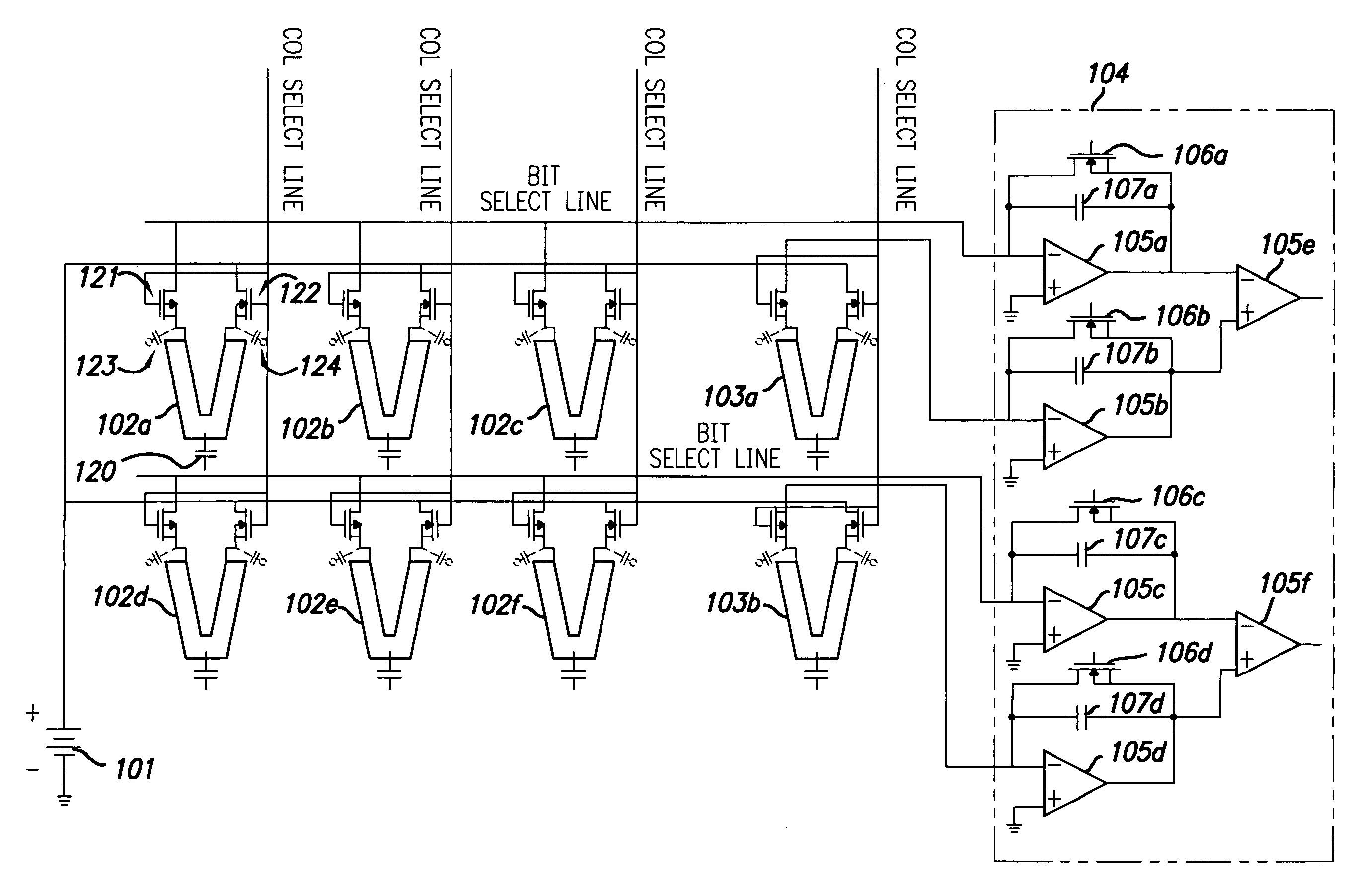
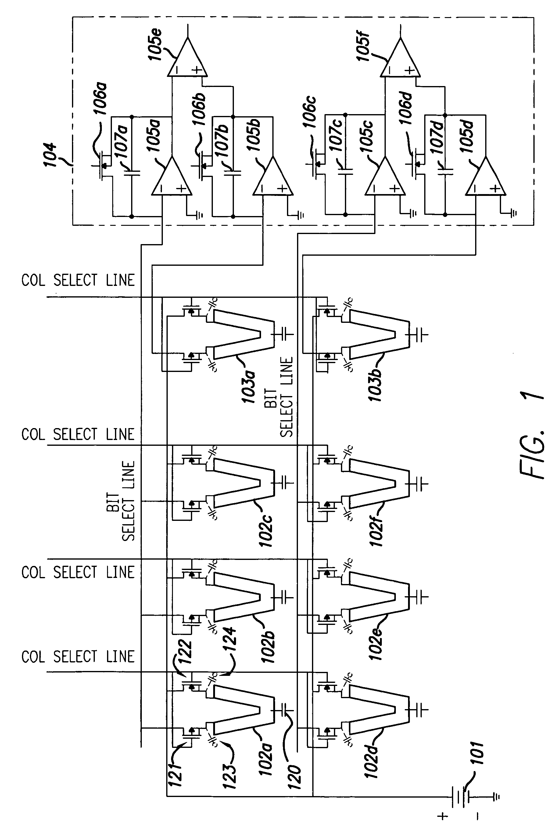
[0027]FIG. 1 illustrates a cantilever array arrangement that operates to charge signal capacitance to a voltage and subsequently release the stored charge into a charge pre-amplifier. From FIG. 1, column select lines and bit select lines pass vertically and horizontally, respectively, to an array of cantilevers. A pre-charge bias is provided by DC voltage source 101, which is typically controllable to offer more than one voltage level. Cantilevers 102a, 102b, and 102c are on one bit line, while cantilevers 102d, 102e, and 102f are on another bit line in the configuration shown. Cantilevers / probes 102a–f form part o...


PUM

PropertyMeasurementUnit
thermal time constantaaaaaaaaaa
capacitanceaaaaaaaaaa
voltageaaaaaaaaaa

Abstract

A method and apparatus for reading data bits stored on a storage medium is provided. The apparatus comprises a data probe structure including a data probe and at least one switch attached to the data probe, a controllable voltage source configured to supply voltage to the data probe structure, and a charge amplification structure configured to receive charge from the data probe structure. The controllable voltage source applies a first voltage to the data probe structure and subsequently applies a second voltage to the data probe structure, thereby causing a sense capacitance to charge and then discharge into the charge amplification structure. Certain embodiments of the design may employ dummy cells, diodes in place of switches, and may use a single line to control voltage switching. A lock-in amplifier approach is also presented.

Description

BACKGROUND OF THE INVENTION[0001]1. Field of the Invention[0002]The present invention relates generally to the field of data storage, and more particularly to the facilitating readout from a data storage device.[0003]2. Description of the Related Art[0004]Storage media for computers and other types of electronic devices include volatile memory and non-volatile memory. Volatile memory loses its contents when power is no longer supplied to the memory, whereas non-volatile memory maintains its contents even when power is not supplied to the memory. The most common type of volatile memory is dynamic random-access memory (DRAM), commonly available as and implemented as an integrated circuit (IC). Non-volatile memory has been available in the form of magnetic and optical media, including hard disk drives, floppy disks, compact disc read-only memories (CD-ROMs), CD re-writable (CD-RW) discs, and digital versatile discs (DVDs), among others. Historically, non-volatile memory implemented as ...

Claims


Application Information

Patent Timeline
Patent Type & Authority Patents(United States)
IPC IPC(8): G11B7/00
CPCG11B9/07G11B9/14G11B11/002G11C8/08B82Y10/00G01Q80/00
Inventor GIBSON, GARYKIYAMA, LENNIE
Owner HEWLETT PACKARD DEV CO LP
Why Eureka
Try Eureka