Patient positioning device and patient positioning method

a positioning device and positioning method technology, applied in the field of patient positioning devices and positioning methods, can solve the problems of deterioration of accuracy, inconvenient positioning of patients, and inability to align and offset the respective positions designated on the drr and the captured image, so as to improve the accuracy of positioning patients, avoid the effect of positioning information and increase the accuracy of positioning

Inactive Publication Date: 2007-05-01
HITACHI LTD
View PDF17 Cites 228 Cited by
  • Summary
  • Abstract
  • Description
  • Claims
  • Application Information

AI Technical Summary

Benefits of technology

[0010]Accordingly, it is an object of the present invention to provide a patient positioning device and a patient positioning method, which can increase the accuracy in positioning of a patient.
[0011]To achieve the above object, the present invention is featured in that a processing unit executes pattern matching between a part of first image information in a first set area including an isocenter, the first image information representing a tumor in the body of the patient and serving as a reference including the isocenter, and a part of second image information in a second set area including a position corresponding to a path of a charged particle beam, the second image information representing a portion of the patient lying across the path of the charged particle beam, thereby producing information used for positioning of the patient (couch). Since the positioning information is produced through the pattern matching between the first image information in the first set area and the second image information in the second set area, accuracy in producing the positioning information is avoided from being affected by the skill of an operator, such as required when designating the positions of monuments, unlike the case of producing the positioning information based on the positions of monuments designated by the operator. As a result, the positioning accuracy can be increased regardless of the skills of individual operators.

Problems solved by technology

In spite of the operator having intended to designate the same positions of the same plural monuments on both the screen images, therefore, there is a fear that the respective corresponding positions designated on the DRR and the captured image are not in alignment and offset from each other.
If the respective designated positions to be kept in alignment on the DRR and the captured image are offset from each other, deterioration of accuracy occurs in aligning the patient couch (particularly the tumor), which should be properly positioned based on both the designated positions, with the beam line.

Method used


Image

  • Patient positioning device and patient positioning method
  • Patient positioning device and patient positioning method
  • Patient positioning device and patient positioning method

Examples


Embodiment Construction

[0025]One embodiment of the present invention will be described below with reference to the drawings.

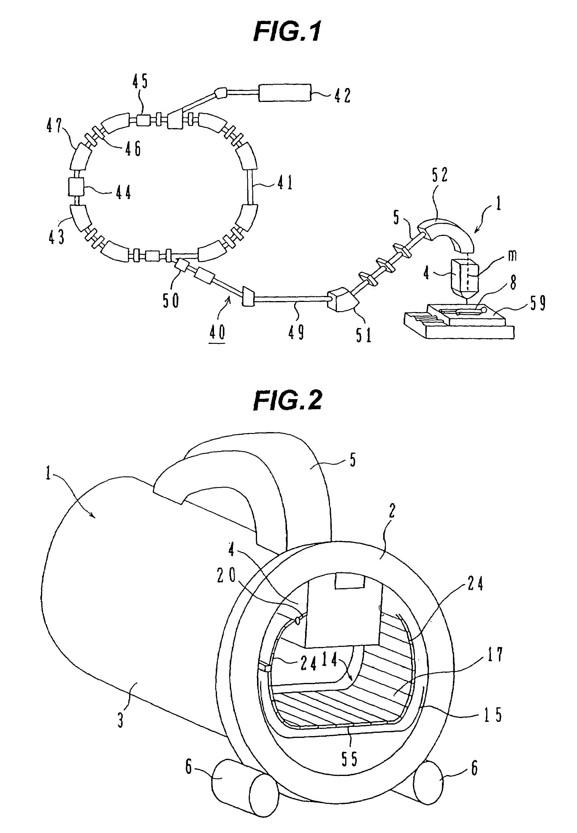
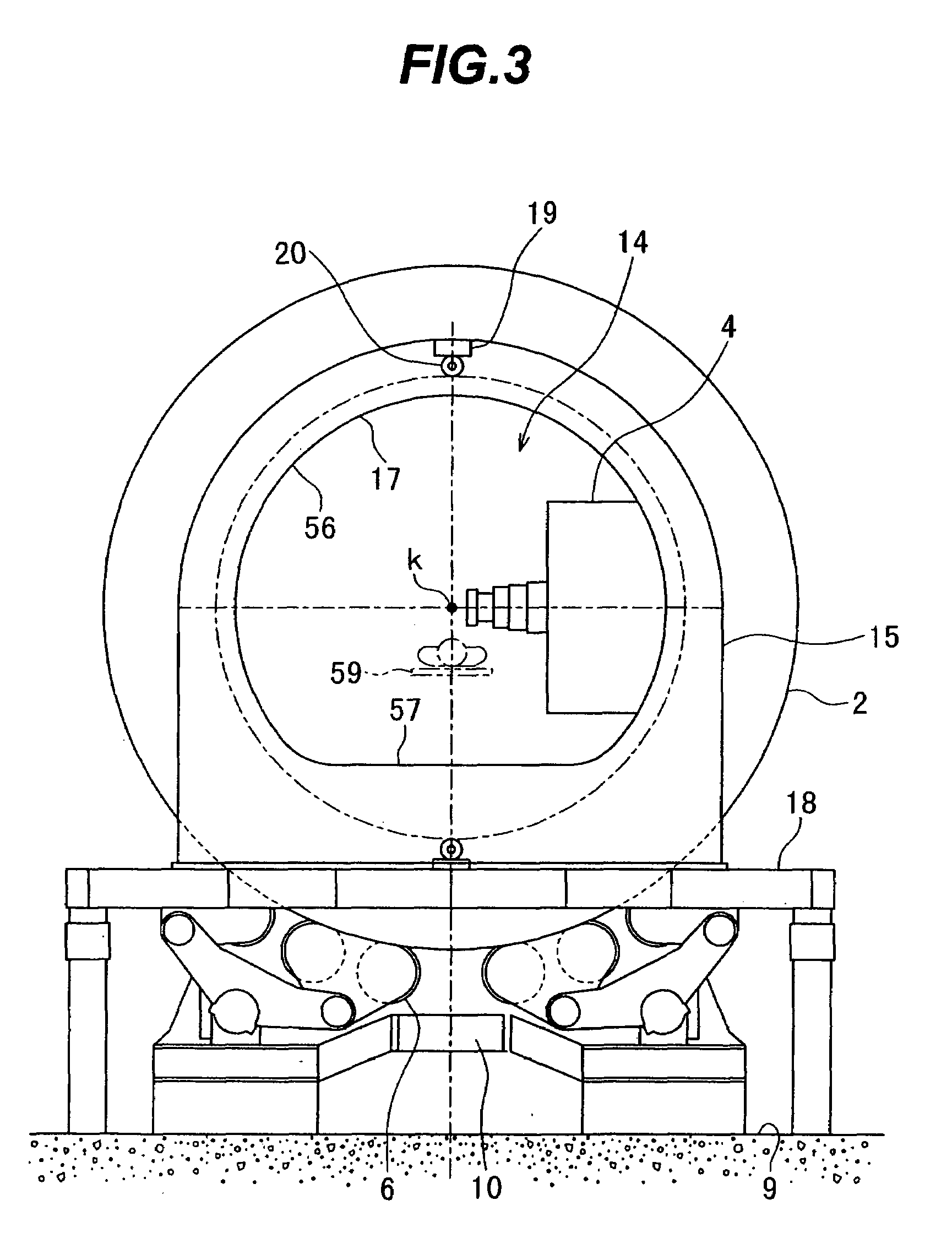
[0026]With reference to FIGS. 1 and 2, a description is first made of a medical particle beam irradiation system to which a patient positioning device of this embodiment is applied.

[0027]A medical particle beam irradiation system 40 comprises a charged particle beam generator 41 and a rotating gantry 1. The charged particle beam generator (also called a particle beam generator) 41, an ion source (not shown), a pre-stage accelerator 42, and a synchrotron 43. Ions (e.g., proton ions or carbon ions) generated from the ion source are accelerated by the pre-stage accelerator (e.g., a linear accelerator) 42. An ion beam (proton beam) accelerated by the pre-stage accelerator 42 enters the synchrotron 43. In this embodiment, a proton beam is employed as the ion beam. The ion beam in the form of a charged particle beam (also called a particle beam) is accelerated by being given with energy ap...


PUM


Abstract

The invention is intended to always ensure a sufficient level of patient positioning accuracy regardless of the skills of individual operators. In a patient positioning device for positioning a patient couch 59 and irradiating an ion beam toward a tumor in the body of a patient 8 from a particle beam irradiation section 4, the patient positioning device comprises an X-ray emission device 26 for emitting an X-ray along a beam line m from the particle beam irradiation section 4, an X-ray image capturing device 29 for receiving the X-ray and processing an X-ray image, a display unit 39B for displaying a current image of the tumor in accordance with a processed image signal, a display unit 39A for displaying a reference X-ray image of the tumor which is prepared in advance, and a positioning data generator 37 for executing pattern matching between a comparison area A being a part of the reference X-ray image and including an isocenter and a comparison area B or a final comparison area B in the current image, thereby producing data used for positioning of the patient couch 59 during irradiation.

Description

CROSS-REFERENCE TO RELATED APPLICATIONS[0001]This application is a continuation of U.S. patent application Ser. No. 10 / 767,330, filed Jan. 30, 2004, which claims priority under 35 USC 119 to Japanese Application No. 2003-058199, dated Mar. 5, 2003, which are incorporated herein by reference.BACKGROUND OF THE INVENTION[0002]1. Field of the Invention[0003]The present invention relates to a patient positioning device and a patient positioning method. More particularly, the present invention relates to a patient positioning device and a patient positioning method, which are suitably employed in a particle beam treatment system for irradiating a charged particle beam (ion beam), such as a proton and a carbon ion, to a tumor for treatment.[0004]2. Description of the Related Art[0005]There is known a treatment method of setting an isocenter (irradiation target center) at a tumor, e.g., a cancer, in the body of a patient and irradiating an ion beam, such as a proton, to the tumor. An appara...

Claims


Application Information

Patent Timeline
Patent Type & Authority Patents(United States)
IPC IPC(8): A61N5/10A61B6/04
CPCA61B6/04A61B6/469A61N5/1049A61N5/1069A61N2005/1061A61N2005/1062A61N2005/1087E05B65/0025
Inventor NAGAMINE, YOSHIHIKOFUJITAKA, SHINICHIROHONDA, TAKUROUAKIYAMA, HIROSHI
Owner HITACHI LTD
Why Eureka
Try Eureka