Transmission device and delay time adjustment method thereof

a delay time and delay technology, applied in the field of transmitters, can solve the problems of inconvenient use time reduction, device expansion, and disadvantageous lower power efficiency of linear amplifiers than those of class c or class, and achieve the effect of reducing the distortion of output signals

Inactive Publication Date: 2007-05-01
III HLDG 12 LLC
View PDF25 Cites 28 Cited by
  • Summary
  • Abstract
  • Description
  • Claims
  • Application Information

AI Technical Summary

Benefits of technology

[0020]According to the above-described structure, the delay time of an amplitude signal path and a phase signal path can be adjusted by the delay unit, so that a distortion generated due to the difference in delay time between both the paths is reduced. Accordingly, the power can be highly efficiently amplified by the high frequency amplifying unit using the phase modulating signal and the amplitude modulating signal. The delay time is adjusted so that a stable signal having little distortion can be outputted.
[0022]According to the above-described structure, the envelope component is negatively fed back by the negative feedback loop to compare the envelope component with the amplitude data. Thus, the amplitude distortion of an output signal can be suppressed. Further, since the delay time of the amplitude signal path and the phase signal path can be adjusted by the delay unit, a distortion generated due to the difference in delay time between both the paths is reduced. In this case, since the loop gain of the negative feedback loop can be lowered, stability can be improved.
[0024]According to the above-described structure, the quantity of delay is switched in accordance with the change of the signal bandwidth of the transmit data. Thus, even when the transmit data having the different signal bandwidth is switched, the delay time of the amplitude signal path and the phase signal path can be adjusted so that a distortion generated due to the difference in delay time between both the paths is reduced. Further, when the negative feedback loop is provided, the delay time is adjusted so as to meet the signal bandwidth. Thus, the stability of the negative feedback loop can be improved.
[0026]According to the above-described structure, the quantity of delay is set in the delay quantity table to read the quantity of delay corresponding to the state of the transmitter so that the delay time of the amplitude signal path and the phase signal path can be adjusted. Thus, under an arbitrary operating state, a distortion generated due to the difference in delay time between the amplitude signal path and the phase signal path can be reduced. Further, when the negative feedback loop is provided, the stability of the negative feedback loop can be improved.
[0028]According to the above-described structure, as the characteristics of the output signal of the high frequency amplifying unit, for instance, a modulation accuracy or the leakage power of adjacent channels or the like is measured. Thus, a quantity of distortion of the output signal can be detected. Accordingly, a proper quantity of delay for reducing the distortion of the output signal of the transmitter is calculated on the basis of the measured result and set to the delay quantity table. Thus, the quantity of delay of the delay unit in the transmitter can be properly adjusted.
[0030]According to the above-described procedure, as the characteristics of the output signal of the high frequency amplifying unit, for instance, a modulation accuracy or the leakage power of adjacent channels or the like is measured. Thus, a quantity of distortion of the output signal can be detected. Accordingly, a proper quantity of delay for reducing the distortion of the output signal of the transmitter is calculated on the basis of the measured result and set to the delay quantity table. Thus, the quantity of delay of the delay unit in the transmitter can be properly adjusted.

Problems solved by technology

However, the power efficiency of the linear amplifier has been disadvantageously lower than that of a class C or an class E non-linear amplifier.
Accordingly, when the linear amplifier is used in a portable radio device such as a portable telephone, a portable information terminal, or the like having a battery as a power source, a using time has been inconveniently decreased.
Further, in a base station device of a mobile telecommunication system in which a plurality of transmitters using a large quantity of power is installed, the device is undesirably enlarged and the quantity of generated heat is inconveniently increased.
However, in the transmitter of the first usual example shown in FIG. 9, since an amplitude signal and a phase signal reach the non-linear amplifying part 115 through different paths, an output signal is undesirably distorted due to the difference of delay time between the signal path of an amplitude modulation and the signal path of a phase modulation.
Accordingly, the stability of the negative feedback loop is disadvantageously deteriorated.

Method used


Image

  • Transmission device and delay time adjustment method thereof
  • Transmission device and delay time adjustment method thereof
  • Transmission device and delay time adjustment method thereof

Examples


first embodiment

(First Embodiment)

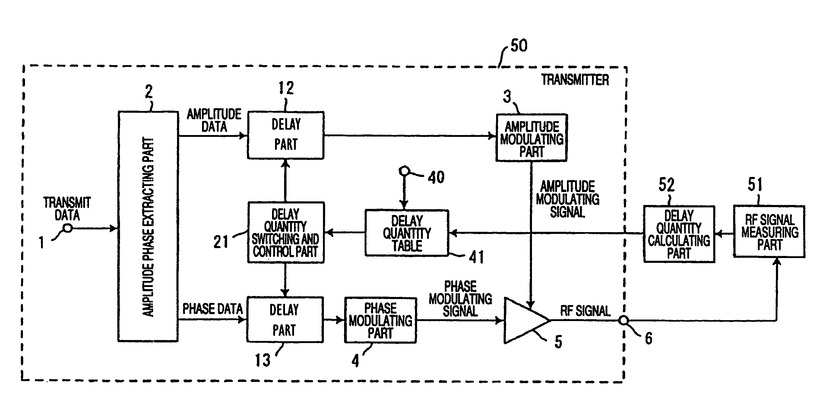
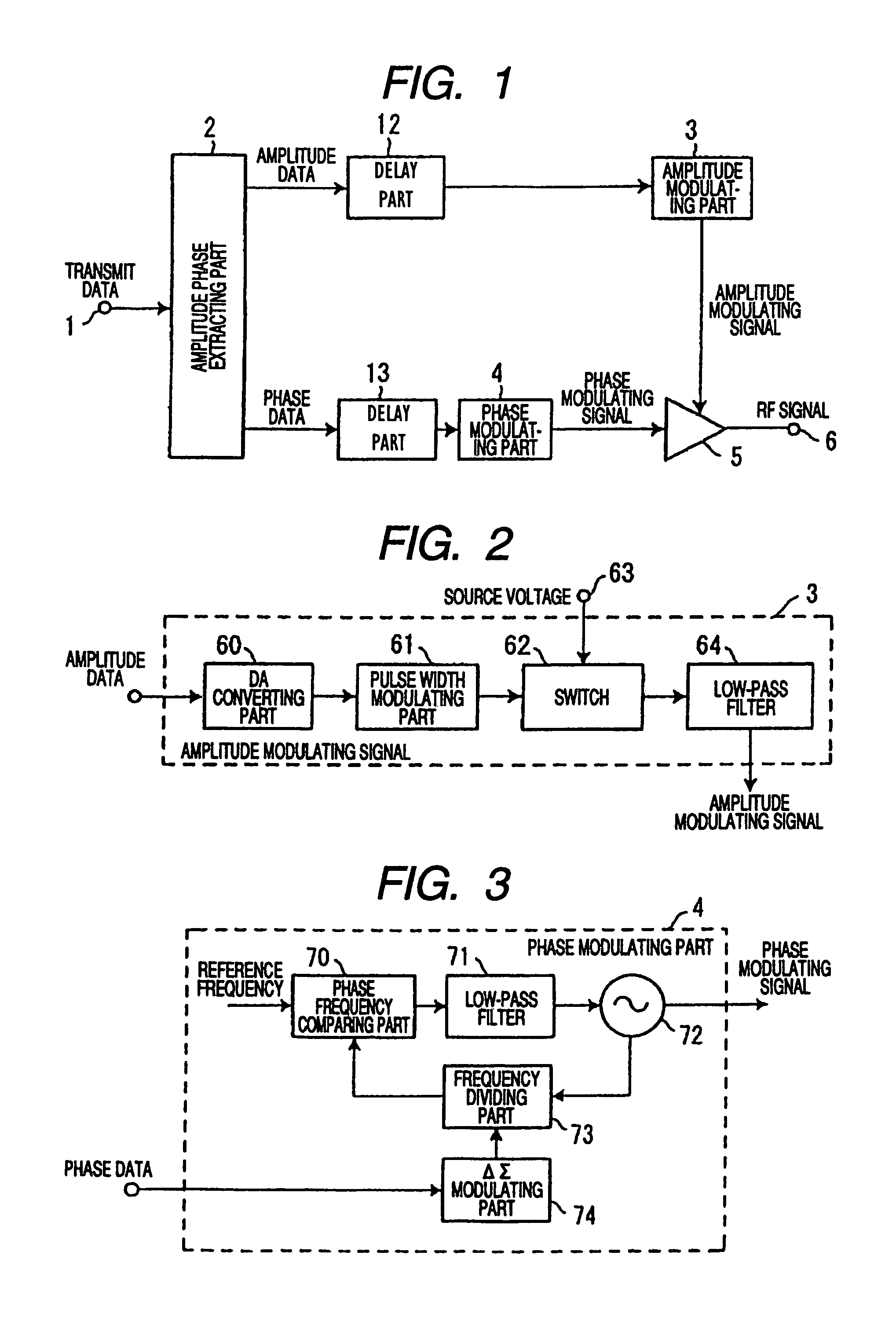
[0043]FIG. 1 is a block diagram showing the structure of main parts of a transmitter according to a first embodiment of the present invention.

[0044]The transmitter of the first embodiment comprises a transmit data input terminal 1, an amplitude phase extracting part (corresponding to an amplitude phase extracting unit) 2, an amplitude modulating part (corresponding to an amplitude modulating unit) 3, a phase modulating part (corresponding to a phase modulating unit) 4, a non-linear amplifying part (corresponding to a high frequency amplifying unit) 5, a transmit output terminal 6 and delay parts (corresponding to delay units) 12 and 13. The transmitter of this embodiment is characterized in that the delay part 12 is provided in a pre-stage of the amplitude modulating part 3 and the delay part 13 is provided in a pre-stage of the phase modulating part 4, respectively.

[0045]In a transmit data signal inputted from the transmit data input terminal 1, amplitude data and...

second embodiment

(Second Embodiment)

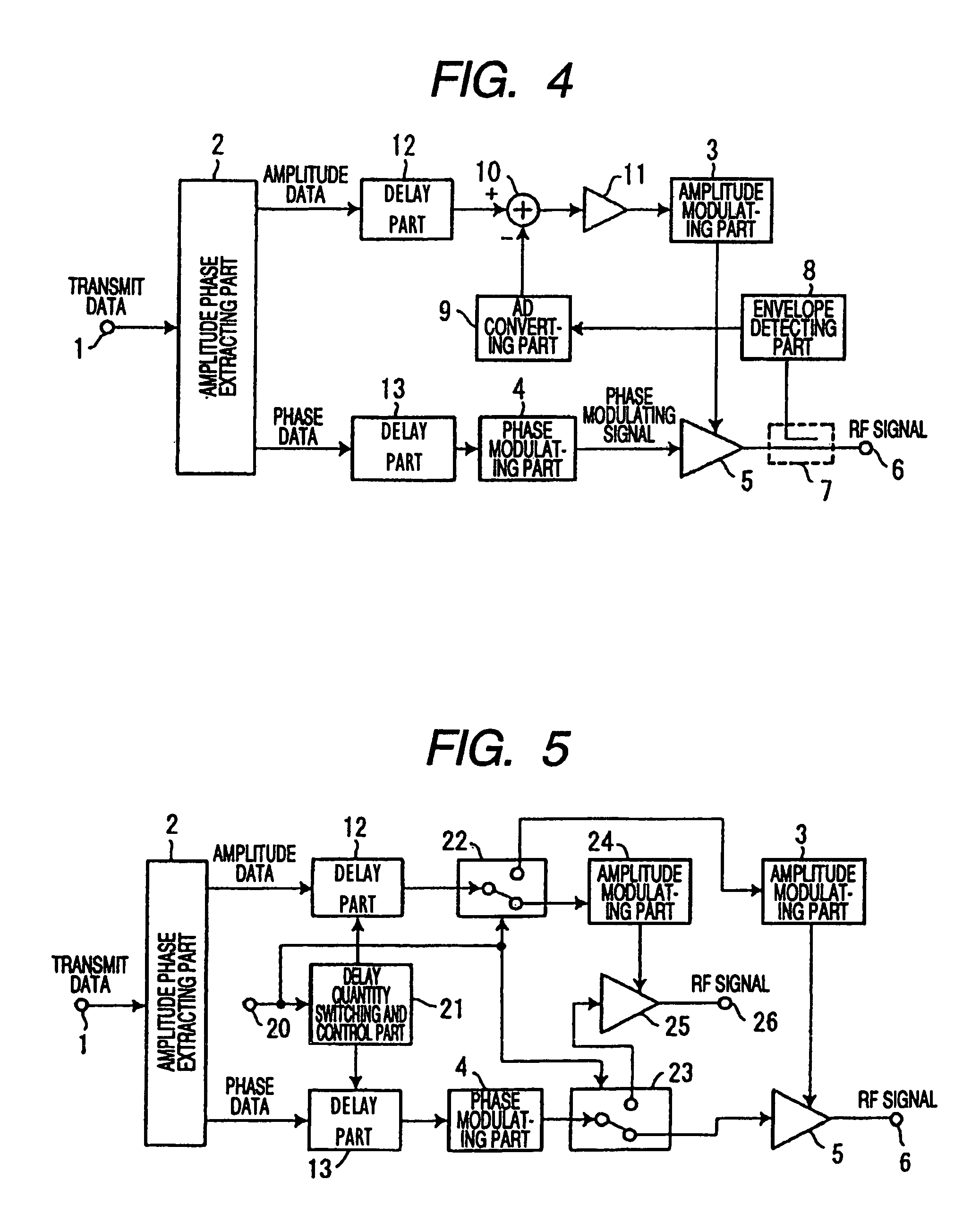
[0057]FIG. 4 is a block diagram showing the structure of main parts of a transmitter according to a second embodiment of the present invention.

[0058]The transmitter of the second embodiment includes a directional coupling part 7, an envelope detecting part (corresponding to an envelope detecting unit) 8, an AD converting part (analog-digital converting part) 9, an adding part 10 and an amplifying part 11 in addition to the structure of the first embodiment shown in FIG. 1. Other structures are the same as those of the first embodiment and the same components are designated by the same reference numerals and the explanation thereof is omitted.

[0059]In the second embodiment, an envelope component of an RF signal as the output of a non-linear amplifying part 5 is fed back in addition to the operation of the first embodiment. A part of a signal component of the output of the non-linear amplifying part 5 is allowed to branch by the directional coupling part 7 and input...

third embodiment

(Third Embodiment)

[0063]FIG. 5 is a block diagram showing the structure of main parts of a transmitter according to a third embodiment of the present invention.

[0064]The transmitter of the third embodiment includes a control signal input terminal 20 for inputting delay and signal path switching and control signals, a delay quantity switching and control part (corresponding to a delay quantity switching and control unit) 21, an amplitude data path switching part 22, a phase data path switching part 23, a second amplitude modulating part 24, a second non-linear amplifying art 25 and a second transmit output terminal 26 in addition to the structure of the first embodiment shown in FIG. 1. Other structures are the same as those of the first embodiment and the same components are designated by the same reference numerals and the explanation thereof is omitted.

[0065]In the third embodiment, a quantity of delay can be switched in addition to the operation of the first embodiment. The secon...


PUM


Abstract

A transmitter and method to output a stable output signal having low distortion by adjusting a delay time of an amplitude signal path and a phase signal path. In an amplitude phase extracting part, amplitude data and phase data are extracted from a transmit data signal and outputted. The amplitude of the amplitude data is modulated in an amplitude modulating part and an amplitude modulating signal is outputted; the phase of the phase data is modulated and a phase modulating signal is outputted. In a non-linear amplifying part, the phase modulating signal is multiplied by the amplitude modulating signal to output an RF signal with a prescribed gain amplified. A delay part provided in a pre-stage of the amplitude modulating part and a delay part provided in a pre-stage of the phase modulating part, respectively, adjusts the delay time of an amplitude signal path and a phase signal path.

Description

TECHNICAL FIELD[0001]The present invention relates to a transmitter and more particularly to a transmitter including a high frequency power amplifier for amplifying a modulation signal having an envelope variable component with a low distortion and a high efficiency.BACKGROUND ART[0002]For a power amplifier provided in an output part of the transmitter of a radio communication system, the compatibility of a low distortion and a high efficiency is required. The power amplifier has a classification that a transistor is used as a current source or a switch. The amplifier using the transistor as the current source includes an class A amplifier, an class AB amplifier, a class B amplifier and a class C amplifier. Further, the amplifier using the transistor as the switch includes a class D amplifier, an class E amplifier and an class F amplifier.[0003]As the high frequency power amplifier for amplifying a modulation signal including an envelope variable component, an A class linear amplifi...

Claims


Application Information

Patent Timeline
Patent Type & Authority Patents(United States)
IPC IPC(8): H04B1/02H03F1/02H03F1/32H03F3/24H04B1/04
CPCH03F1/0222H03F1/32H03F1/3282H03F3/24H04B1/0475H03F2200/331
Inventor ARAYASHIKI, MAMORU
Owner III HLDG 12 LLC
Why Eureka
Try Eureka