
Electromagnetic clutch

a technology of electromagnetic clutch and clutch, applied in the field of electromagnetic clutch, can solve the problems of increased transmission torque, inability to provide damping effect regarding clutch operation sound and torsional resonance, and inability to provide a damping effect regarding clutch operation and torsional resonance, so as to reduce the operation sound, suppress the increase of the reaction of the spring portion, and increase the initial torque

Inactive Publication Date: 2007-05-08
DENSO CORP
View PDF9 Cites 4 Cited by
  • Summary
  • Abstract
  • Description
  • Claims
  • Application Information

AI Technical Summary

Benefits of technology

[0011]In view of the problems described above, the invention is directed to provide an electromagnetic clutch that can reduce the operation sound, can increase the initial torque, can suppress the increase of the reaction of the spring portion of the plate and can eliminate the necessity for the surface treatment of the plate and the armature.
[0012]According to the present invention, there is provided an electromagnetic clutch of the type in which an armature and a plate sandwich an elastic member between them, a spring portion is formed on the plate and the elastic member is so disposed as to cover a front side of the spring portion, too. Consequently, vibration of the spring portion of the plate when the armature is attracted to a driving side rotary member (rotor) can be damped and the attraction sound can be reduced.
[0013]In the electromagnetic clutch according to the present invention, the elastic member covers, as a whole, the front side of the plate. Accordingly, the attraction sound can be reduced and a surface treatment step of the plate such as rust-proofing can be completely eliminated.
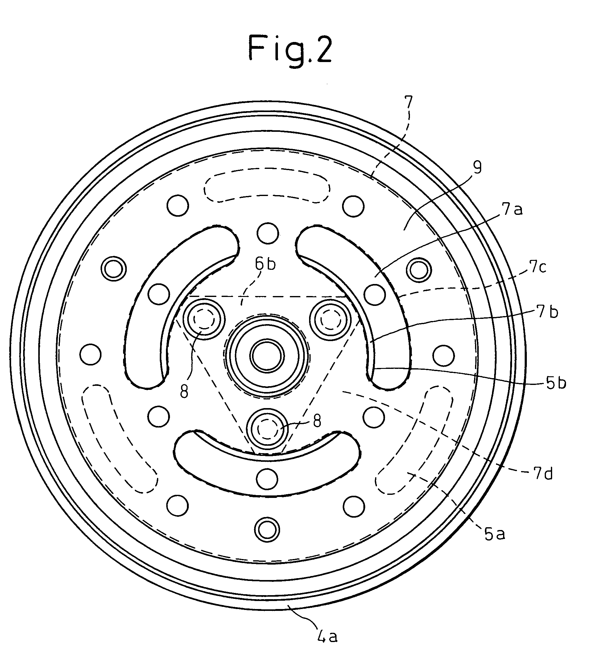
[0015]In the electromagnetic clutch according to the present invention, an outer peripheral edge portion of each aperture is positioned more outward in a radial direction than an inner diameter of the armature. Consequently, the portion corresponding to the gap between the apertures of the plate causes elastic deformation of the elastic member sandwiched between the armature and the plate and the spring portion of the plate can smoothly undergo deflection with the result that the attraction sound can be reduced.
[0016]In the electromagnetic clutch according to the present invention, the elastic member is extended at least to the same plane as an end face of the armature on the rear side or to a position somewhat protruding from the end face of the armature on the rear side. Consequently, the initial transmission torque of the electromagnetic clutch can be increased and the attraction sound between the armature and the driving side rotary member (rotor) can be reduced.

Problems solved by technology

However, it is known that, because the power transmission system from the armature to the hub does not have a damping mechanism of vibration (impact) and torque fluctuation, the hub structure cannot provide a damping effect regarding a clutch operation sound and torsional resonance.
Therefore, there remain the problems that the transmission torque increases with the increase of the number of times of connection / disconnection from the relation of compatibility of the materials besides the occurrence of the operation sound, and the initial transmission torque is lower than the transmission torque after connection / disconnection.
Another problem is that surface treatment is necessary because the raw material of both plate (leaf spring) and armature is iron.
According to this prior art technology, too, the problem yet remains unsolved that the surface treatment is necessary because the leaf spring member (plate) is exposed.
Another problem is that reaction becomes high and an operation factor is deteriorated because the spring portion of the leaf spring member is bonded to the elastic member.
Furthermore, the problem of the impingement sound that occurs when electric power is fed to the electromagnetic coil and the armature is attracted to the rotor is not solved, either, because the armature is so disposed as to face the rotor with a clearance between them.
Further, the problem also remains that when the armature is operated, the leaf spring member vibrates and noise occurs.

Method used


Image

  • Electromagnetic clutch
  • Electromagnetic clutch
  • Electromagnetic clutch

Examples


Embodiment Construction

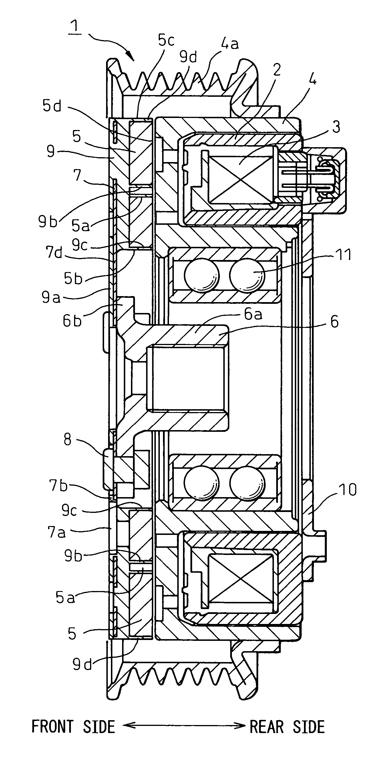
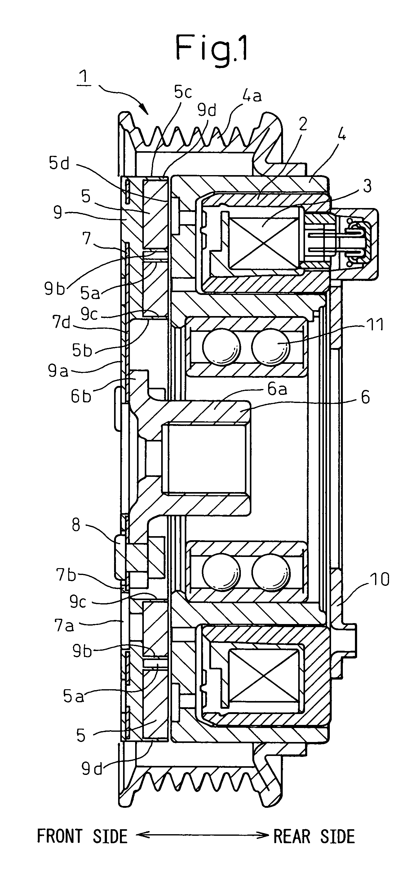
[0027]An electromagnetic clutch according to preferred embodiments of the invention will be hereinafter explained with reference to the accompanying drawings. FIG. 1 is a longitudinal sectional view of the electromagnetic clutch according to the invention. This clutch is appropriately fitted to a refrigerant compressor of a refrigeration cycle of an air conditioner for a vehicle. FIG. 2 is a front view of the electromagnetic clutch. The electromagnetic clutch 1 according to the invention includes an electromagnetic coil 3 accommodated in a stator 2, a rotor 4 as a driving side rotary member driven and rotated by a car engine, not shown in the drawing, an armature 5 attracted to the rotor 4 by the magnetic force generated by the electromagnetic coil 3 and an inner hub 6 as a driven side rotary member interconnected to the armature 5 and rotating integrally with the armature 5.

[0028]The inner hub 6 is interconnected to a rotary shaft (not shown) of a refrigerant compressor as a driven...


PUM


Abstract

An electromagnetic clutch 1 has a construction in which an armature 5 and a plate 7 sandwich an elastic member 9 between them. A spring portion 7d is formed in the plate 7 and an elastic member 9a is so disposed as to cover a front side of the spring portion 7d, too. Elastic members 9b, 9c and 9d are disposed in a thin film form on an inner surface of elongated holes 5a of the armature 5 and the innermost and outermost diameter portions 5b and 5c of the armature 5. The distal end of each elastic member 9b, 9c and 9d is extended to the same plane as an end face 5d of the armature 5 on the rear side or to a position somewhat protruding from the end face on the rear side.

Description

BACKGROUND OF THE INVENTION[0001]1. Field of the Invention[0002]This invention relates to an electromagnetic clutch for transmitting and cutting-off turning power. The invention is suitable for connecting and cutting-off a compressor operation, for a car air conditioner, for example.[0003]2. Description of the Related Art[0004]An electromagnetic clutch for a compressor of a car air conditioner according to the prior art includes a rotor driven and rotated by a driving source such as an engine and an armature so disposed as to face the rotor with a predetermined small clearance between them. A hub structure of a leaf spring type is known as one of the hub structures for interconnecting the armature to a rotary shaft on the compressor side. In this hub structure, one of the ends of a leaf spring is interconnected to an inner hub that is in turn interconnected to the rotary shaft on the compressor side and the other end of the leaf spring is interconnected to the armature.[0005]Because...

Claims


Application Information

Patent Timeline
Patent Type & Authority Patents(United States)
IPC IPC(8): F16D27/112
CPCF16D27/112F16D2027/007B05C9/14F26B3/30F26B19/005
Inventor KONISHI, TOSHIHIROHAYASHI, TOSHIHIRO
Owner DENSO CORP
Learn More