High frequency heating apparatus

a heating apparatus and high frequency technology, applied in the direction of electrical apparatus, electric/magnetic/electromagnetic heating, dielectric heating, etc., can solve the problems of insufficient cooling, inability to produce inability to meet the needs of the inverter power supply, so as to reduce the time spent on forming the air guide portion, the molds can be simplified, and the bending process can be easily performed.

Active Publication Date: 2007-05-08
PANASONIC CORP
View PDF6 Cites 4 Cited by
  • Summary
  • Abstract
  • Description
  • Claims
  • Application Information

AI Technical Summary

Benefits of technology

[0010]It is, therefore, a primary object of the present invention to provide a high frequency heating apparatus capable of cooling down effectively an inverter power supply without increasing capacity of a cooling device.
[0011]It is another object of the present invention to provide a high frequency heating apparatus capable of realizing a high output of the inverter power supply by increasing a cooling efficiency sufficient enough to prevent the inverter power supply from overheating due to the high output thereof.
[0012]It is still another object of the present invention to provide a high frequency heating apparatus in which a holding member is provided with a holding portion for holding the inverter power supply and an air guide portion for guiding a cooling air toward the inverter power supply in order to cool down electric components of the inverter power supply, wherein the air guide portion covers the inverter power supply and a high voltage transformer and, at the same time, guides the cooling air in such a manner that the semiconductor switching device and the high voltage transformer of the inverter power supply are primarily cooled down. As previously described, the semiconductor switching device and the high voltage transformer are exposed to a sufficient amount of the cooling air efficiently enough to be cooled down effectively. Thus, any thermal failure of the semiconductor switching device due to a switching loss is prevented. Moreover, an increase in temperature of a winding of the high voltage transformer is suppressed.

Problems solved by technology

However, in such a conventional structure in which the cooling air uniformly flows throughout the inverter power supply, it is difficult to effectively suppress an increased heat generation of the semiconductor switching device and the semiconductor rectifying device of the inverter power supply due to the increased output, which may cause thermal failures thereof, thereby leading to a malfunction of the inverter power supply.
The increased heat generation, however, cannot be sufficiently cooled down in such a conventional structure, and therefore, the thermal failure of the semiconductor switching device 8 is likely to occur rather frequently.
Accordingly, a time period during which the high output is produced becomes short, thus failing to achieve the fast cooking.
Further, since temperature of winding of high voltage transformer 9 becomes higher, the diameter of the winding is required to be greater, which makes high voltage transformer 9 bulky.
Accordingly, in such a case, inverter power supply 7 and hence the high frequency heating apparatus becomes undesirably larger.
In addition, since a blowing capacity of cooling fan 2 should be increased, wind noise becomes also undesirably increased.

Method used


Image

  • High frequency heating apparatus
  • High frequency heating apparatus
  • High frequency heating apparatus

Examples


embodiment 1

[0047

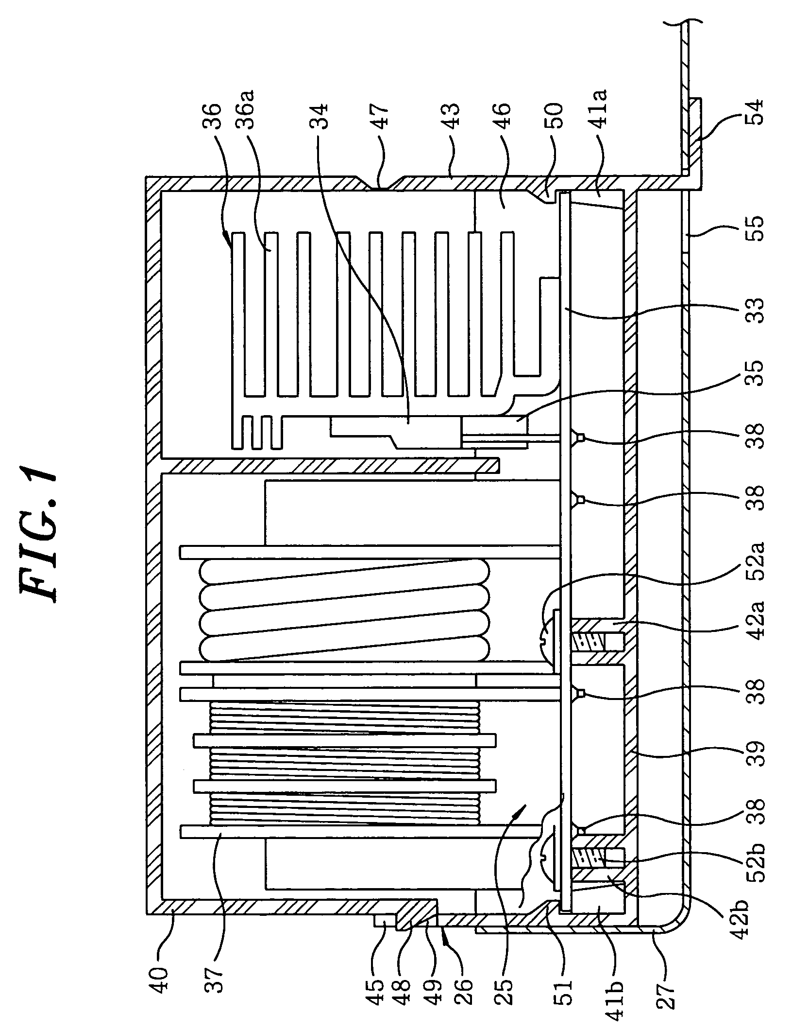
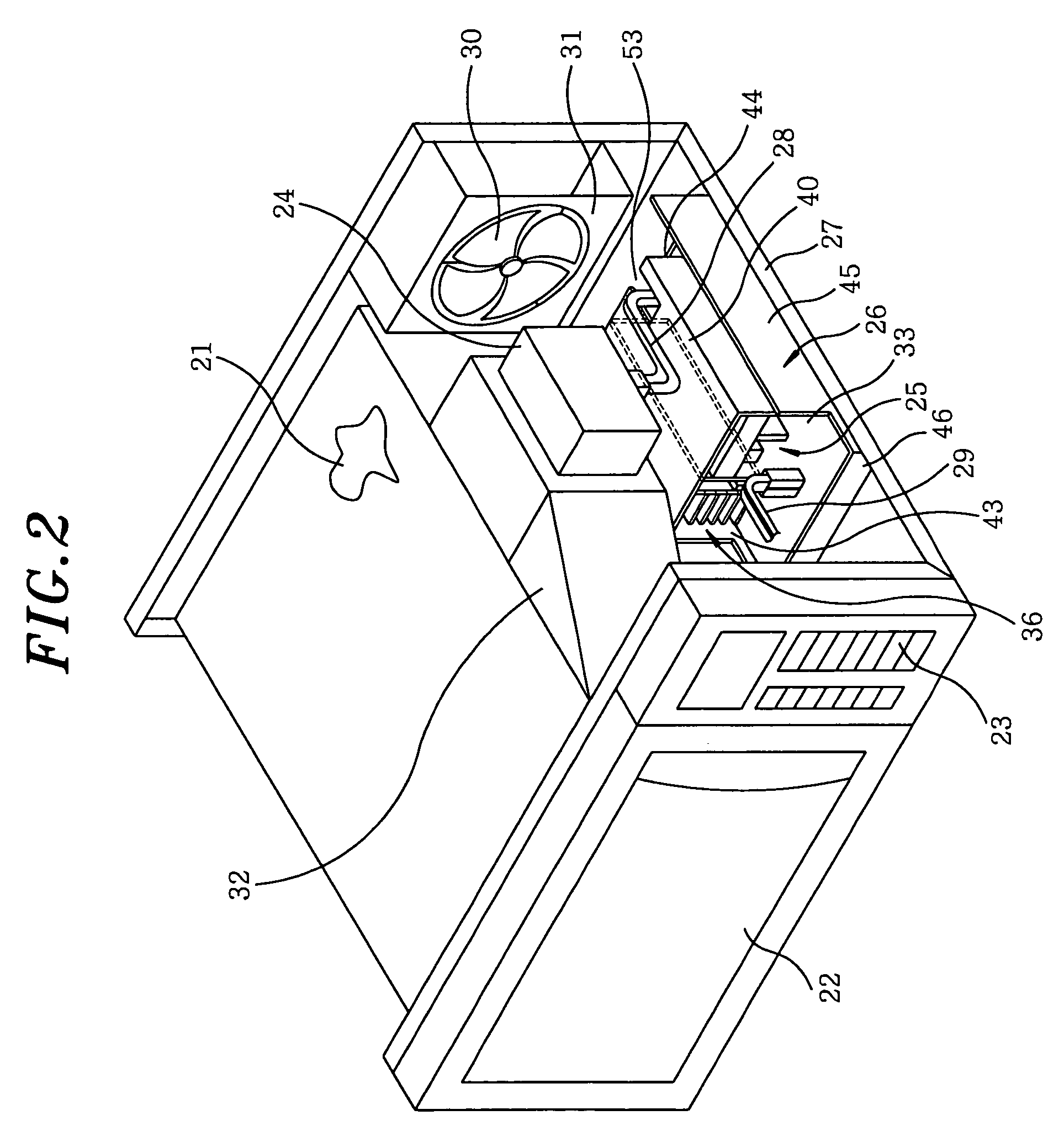
[0048]FIG. 1 illustrates a cross sectional view of main parts of a high frequency heating apparatus in accordance with a first embodiment of the present invention. FIG. 2 describes a perspective view showing an external appearance of the high frequency heating apparatus of the first preferred embodiment with its casing (not shown) removed.

[0049]As shown in FIGS. 1 and 2, mounted at a front side of heating chamber 21 is door 22 for opening and closing heating chamber 21. Control panel 23 for setting heat output, heating time and the like is disposed beside door 22. Magnetron 24 is mounted on a right side wall of heating chamber 21. Under magnetron 24, inverter power supply 25 is secured to holding member 26, which is fixed on bottom plate 27 of the high frequency heating apparatus. Inverter power supply 25 is connected to magnetron 24 via high voltage lead wires 28 for supplying high voltage thereto. Inverter power supply 25 is also connected to a control board of control panel ...

embodiment 2

[0058

[0059]Referring to FIG. 3, there is shown a cross sectional view of main parts of a high frequency heating apparatus in accordance with a second embodiment of the present invention, wherein like parts to those of the first embodiment are represented by like reference characters and detailed descriptions thereof will be omitted.

[0060]Disposed vertically on both sides of holding member 26a are walls 61 and 62 which have at their top end portions recessed engaging portions 63a and 63b, respectively. In order to efficiently cool down cooling fin member 36 coupled with semiconductor switching device 34 and rectifying device 35, and high voltage transformer 37, air guide portion 64 having a substantially E-shaped configuration in section is introduced, which has at its both end portions protruded engaging portions 65a, 65b. Protruded engaging portions 65a, 65b of air guide portion 64 are engaged with corresponding recessed engaging portions 63a and 63b of walls 61, 62 in such a manne...

embodiment 3

[0066

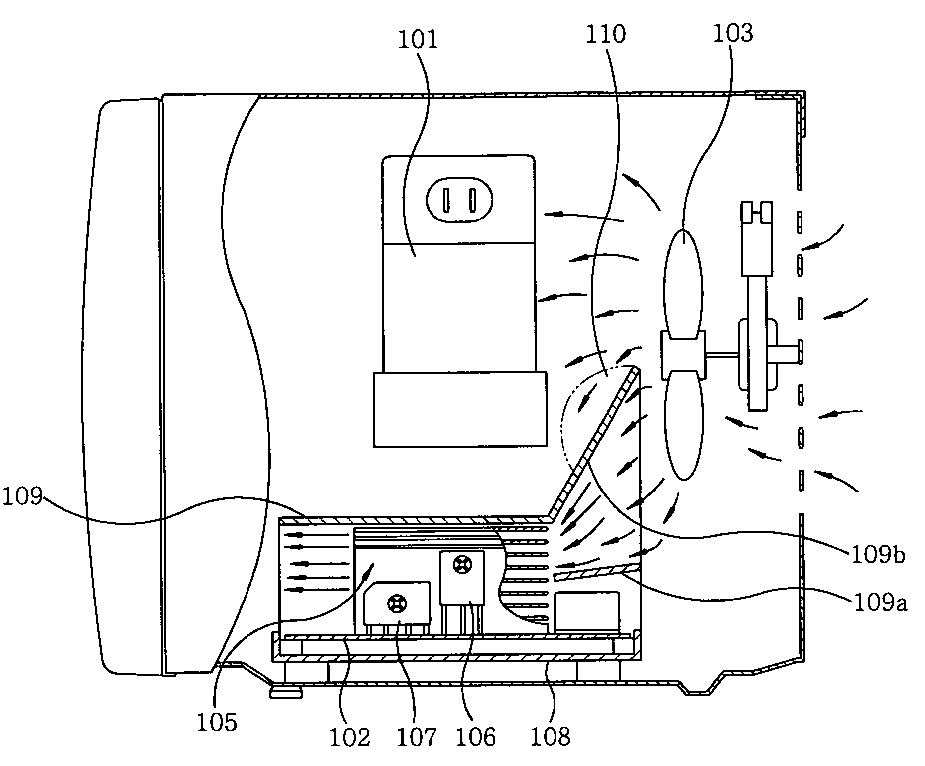
[0067]Referring to FIGS. 4 to 6, there is illustrated a high frequency heating apparatus in accordance with a third embodiment of the present invention. FIG. 4 shows a partial cross-sectional view of the third embodiment; FIG. 5 displays the wind speed and wind pressure of cooling air blown from a cooling fan; and FIG. 6 sets forth an enlarged perspective view of an air guide portion and an inverter power supply.

[0068]As shown in FIG. 4, there are presented magnetron 101, inverter power supply 102 and cooling fan 103. Mounted on inverter power supply 102 is cooling fin member 105 with which semiconductor switching device 106 and semiconductor rectifying device 107 are coupled. Moreover, air guide portion 109 and holding portion 108 on which inverter power supply 102 is mounted are formed in a single body. Air guide portion 109 is provided with inner partition 109a and outer partition 109b, which form a convergent passage for guiding cooling air from cooling fan 103. Inner parti...


PUM


Abstract

A heating apparatus includes an inverter power supply for driving the high frequency generating device, a holding member for holding the inverter power supply and cooling fan for cooling down the inverter power supply. The holding member is provided with a holding portion for holding the inverter power supply and an air guide portion for guiding cooling air from the cooling fan toward the inverter power supply, and the air guide portion covers the inverter power supply and guides the cooling air in a manner that a semiconductor switching device and a high voltage transformer of the inverter power supply are primarily cooled down.

Description

FIELD OF THE INVENTION[0001]The present invention relates to a high frequency heating apparatus such as a microwave oven; and more particularly, to an internal structure of a high frequency heating apparatus capable of effectively cooling down a semiconductor switching device and a high voltage transformer of an inverter power supply for driving a high frequency heating source such as a magnetron.BACKGROUND OF THE INVENTION[0002]Referring to FIGS. 8 and 9, there is illustrated a schematic cross-sectional view of a conventional high frequency heating apparatus. On a rear wall of casing 1, cooling fan 2 is mounted. Disposed above and in front of cooling fan 2 is magnetron 3 to which blast duct 5 for guiding cooling air to heating chamber 4 and air guide 6 for guiding cooling air to magnetron 3 are mounted. Disposed under magnetron 3 is inverter power supply 7 on which semiconductor switching device 8 and high voltage transformer 9 are mounted adjacent to cooling fan 2. Cooling guide 1...

Claims


Application Information

Patent Timeline
Patent Type & Authority Patents(United States)
IPC IPC(8): H05B6/64H05B6/72H05B6/80
CPCH05B6/642H05B6/72
Inventor YAMAGUCHI, TAKAHIDEYAMAMOTO, KOJI
Owner PANASONIC CORP
Why Eureka
Try Eureka