Method for operating optical sensors

a technology of optical sensors and optical sensors, applied in the direction of instruments, using electrical/magnetic means, geological measurements, etc., can solve the problems of cumbersome, correspondingly expensive, and inability to constant measurement accuracy

Active Publication Date: 2007-05-08
SICK AG
View PDF2 Cites 76 Cited by
  • Summary
  • Abstract
  • Description
  • Claims
  • Application Information

AI Technical Summary

Benefits of technology

[0005]Based on this state of the art, it is an object of the invention to provide an improved method and sensor which are more diversified and can cover larger measurement ranges.
[0007]In this way, a large measurement range can be covered by a single sensor. The use of different sensors for different conveyance speeds, for example, is no longer necessary.
[0013]Especially when the external condition is detected automatically, it is advantageous that the scale value is also switched automatically as a function of the external condition, for then no manual intervention is required and the entire measurement process occurs automatically with the desired measurement accuracy.

Problems solved by technology

A problem occurs when the measurement accuracy cannot be constant because it is influenced by external conditions.
Thus, the measurement layout at the conveyor either has a limited range of application or it must have several sensors with different scale values, which is correspondingly expensive and cumbersome.

Method used


Image

  • Method for operating optical sensors
  • Method for operating optical sensors
  • Method for operating optical sensors

Examples


Embodiment Construction

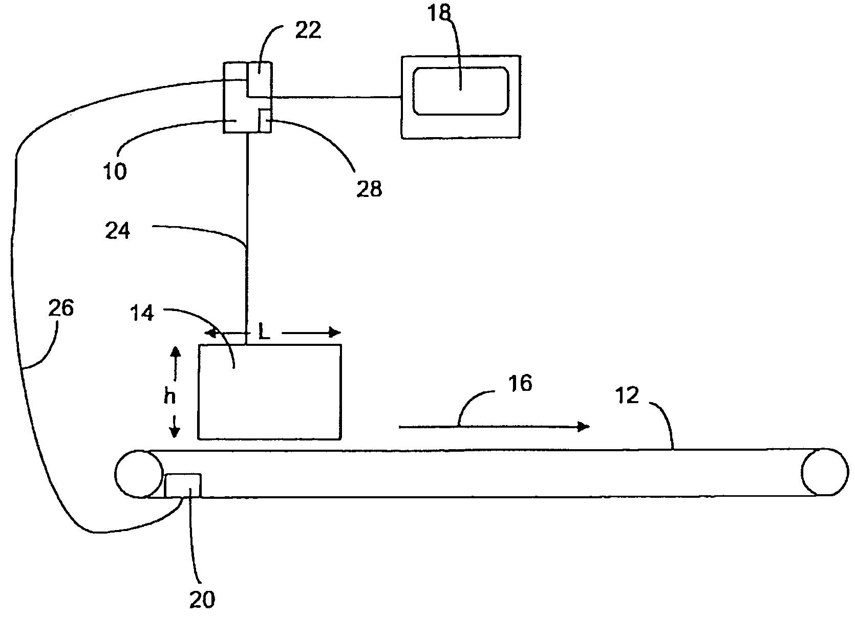
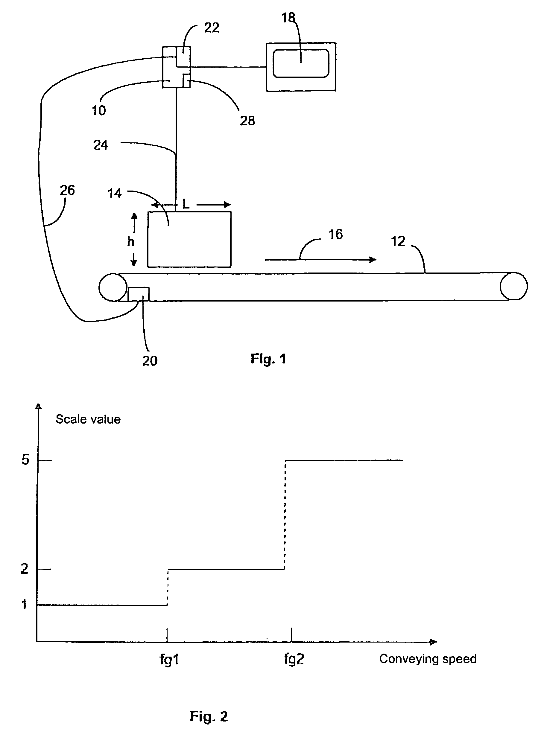
[0025]An optoelectronic sensor 10 according to the invention is arranged above a conveyor 12, on which goods such as packages 14 are being transported in any desired direction 16. The packages 14 are automatically measured by the sensor 10 during their transport to determine their volume. The measurement results can be indicated on a display unit 18 and / or they can be fed to a suitable signal output for further processing.

[0026]The optoelectronic sensor 10 can be a laser scanner, such as is marketed by the assignee of this invention, SICK AG of Germany, under the designation LMS 200, which scans the package 14 in familiar manner with a laser beam 24. The volume can ultimately be determined from the angle and distance information of the reflected laser beam.

[0027]When determining the volume of a square-shaped package 14, it is necessary to determine its height h, width and length L. The accuracy of the length measurement in the transport direction 16 is, as mentioned above, dependent...


PUM

PropertyMeasurementUnit
physical quantityaaaaaaaaaa
speedaaaaaaaaaa
lengthaaaaaaaaaa

Abstract

A method for operating an optical sensor for measuring a physical quantity with a defined scale value that is subject to a calibration certification. The measurement accuracy of the quantity being measured is dependent on at least one external condition, and a given scale value is used for the measurement according to the desired measurement accuracy. The scale value is appropriately changed when the measurement accuracy changes due to a change of external condition. An optoelectronic sensor has a switching arrangement for changing the scale value. The sensor is more diversified and can cover larger measurement ranges without requiring new certifications or authorizations for the different measurement ranges.

Description

BACKGROUND OF THE INVENTION[0001]The invention concerns a method for operating an optical sensor for measuring a physical quantity, as well as the corresponding sensor.[0002]In general, one must define a so-called scale value for measurement devices with which a physical parameter is being measured and which operate pursuant to a calibration certificate. The scale value corresponds to the smallest indicated dimensional unit and is used to define the measurement accuracy. The measurement results may only be indicated in multiples of the scale value. By definition, scale values should only be selected in steps of 1, 2 and 5 times 10n (n is an integer). The definition is mandated by national authorities, for example, in Germany, by the Physikalisch Technische Bundesanstalt, which follow the recommendations of the OIML (International Organization of Legal Metrology).[0003]Each calibrated measurement device has one of these scale values and is suitable for applications with a measurement...

Claims


Application Information

Patent Timeline
Patent Type & Authority Patents(United States)
IPC IPC(8): G01N21/86G01N21/88G01V8/00G01B11/04
CPCG01B11/04
Inventor SCHOPP, THOMAS
Owner SICK AG
Why Eureka
Try Eureka