Micromechanical electrostatic resonator

a micro-mechanical and electrostatic resonator technology, applied in the direction of soldering apparatus, instruments, manufacturing tools, etc., can solve the problems of high frequency of the vibration body, large capacitance, and difficulty in designing low voltage and low power consumption, and achieve low cost and high efficiency.

Inactive Publication Date: 2007-05-08
SEIKO EPSON CORP
View PDF9 Cites 123 Cited by
  • Summary
  • Abstract
  • Description
  • Claims
  • Application Information

AI Technical Summary

Benefits of technology

[0011]Further, in the micromechanical electrostatic resonator including the above-mentioned related art comb teeth-shaped structure, by adapting the comb teeth-shaped structure, the capacitance between a drive electrode and a movable electrode becomes large. Further, by adapting the comb teeth-shaped structure, the planar projection areas of the drive electrode and the movable electrode become large, and thus the capacitance between the electrodes and the substrate increases.
[0054]In the present embodiment, preferably, the second substrate includes a silicon substrate, an insulating film formed on the silicon substrate, and the active layer formed on the insulating film, and the thinning is removing the silicon substrate by performing a polishing treatment or an etching treatment on the silicon substrate included in the second substrate. According to this construction, at least one of the polishing treatment and the etching treatment is performed on the silicon substrate which is provided on the second substrate, which is joined to the first substrate, to thereby remove the silicon substrate. Thus, it is possible to precisely form the active layer and the insulating film each having the predetermined thickness on the first substrate.

Problems solved by technology

However, since a realizable vibration frequency is normally low in a range of about tens kHz to hundreds kHz, in particular, several MHz at most, there is a problem in that higher frequency of the vibration body is difficult.
Since it is difficult to make a fine structure due to increase of resistance of a wiring line or conductive connection, the capacitance becomes relatively large as the electrode structure of the micromechanical electrostatic resonator is finely constructed.
Thus, it is difficult to design low voltage and low power consumption.
This is a serious hindrance to practical use and commercialization of product.

Method used


Image

  • Micromechanical electrostatic resonator
  • Micromechanical electrostatic resonator
  • Micromechanical electrostatic resonator

Examples


first exemplary embodiment

[First Exemplary Embodiment]

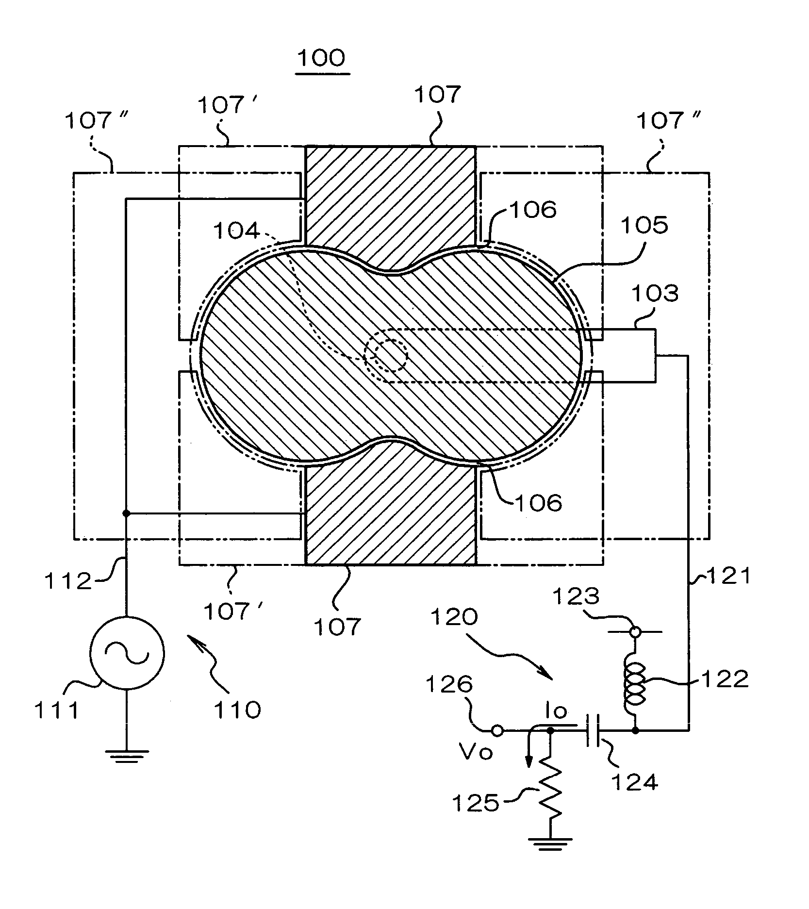
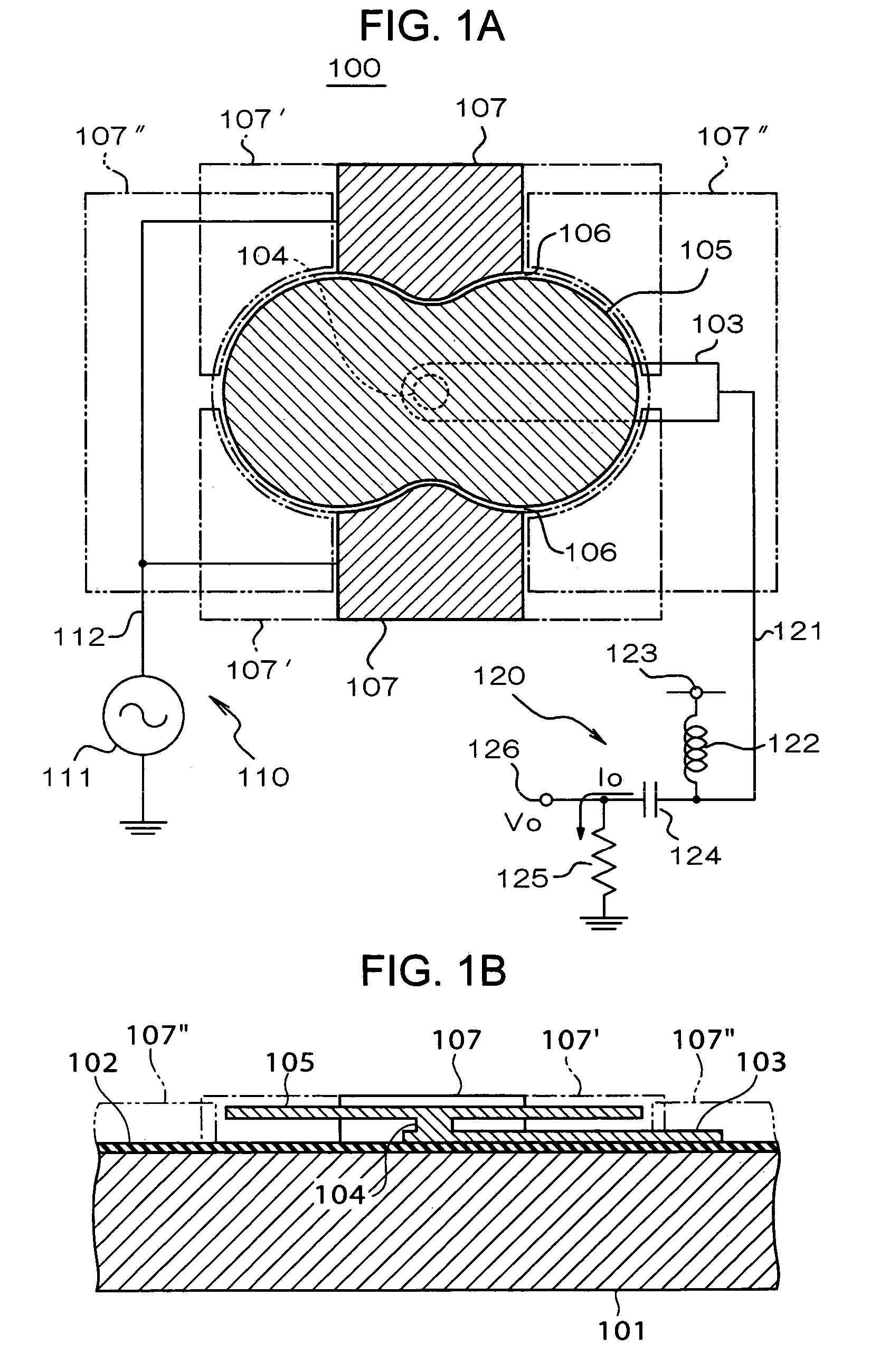
[0089]Next, a first exemplary embodiment of the present invention will be described with reference to the attached drawings. FIG. 1 shows a structure of a micromechanical electrostatic resonator 100 according to the first exemplary embodiment of the present invention, together with a circuit construction, and FIG. 1(A) is a schematic plan view and FIG. 1(B) is a schematic longitudinal cross-sectional view.

[0090]In the micromechanical electrostatic resonator 100, as occasions arise, an insulating film 102 to isolate a resonator structure is formed on a surface of a substrate 101 made of a silicon substrate or the like. On the substrate 101 or the insulating film 102, an output electrode 103, a supporting portion 104 and a vibration body 105 are constructed. Further, at both sides of the vibration body 105 (in the example shown in the drawing, upper and lower sides in FIG. 1(A) or front and back sides in FIG. 1(B)), a pair of excitation electrodes 107 and 1...

second exemplary embodiment

[Second Exemplary Embodiment]

[0099]Next, the micromechanical electrostatic resonator 200 according to a second exemplary embodiment of the present invention will be described with reference to FIGS. 3A–B. The resonator 200 has the vibration body 205 having the approximately same planar shape as that of the vibration body in the first exemplary embodiment. However, the vibration body 205 in the second exemplary embodiment is different from the vibration body 105 in the first exemplary embodiment in that a center portion of a pair of neck portions is connected to the beam-shaped supporting portion 204. The supporting portion 204 supports the vibration body 205 from both sides in a beam shape and is constructed to be stretched approximately horizontally (that is, in parallel to the surface of the substrate 201). Further, another end of the supporting portion 204 is connected to the output electrode 203.

[0100]Further, in the present exemplary embodiment, a pair of excitation electrodes ...

third exemplary embodiment

[Third Exemplary Embodiment]

[0110]FIGS. 7A–C show a structure of the micromechanical electrostatic resonator 300 according to a third exemplary embodiment of the present invention. FIG. 7(A) is a schematic longitudinal cross-sectional view, FIG. 7(B) is a schematic plan view and FIG. 7(C) is a schematic expanded perspective view showing the shape of the vibration body 305. In the electrostatic resonator 300, the insulating layer 302 is formed on the substrate 301 and the resonator structure is formed on the insulating layer 302. The substrate 301 is preferably the semiconductor substrate such as silicon single crystal or compound semiconductor such as GaAs or InP, but it may be constructed with other materials such as glass, quartz, ceramics or synthetic resin. Further, the insulating layer 302 is not needed when the substrate 301 is made of the insulator. However, when the substrate 301 is made of semiconductor or conductor, or when the substrate 301 is made of the insulator with a...


PUM

PropertyMeasurementUnit
diameteraaaaaaaaaa
diameteraaaaaaaaaa
densityaaaaaaaaaa

Abstract

Exemplary embodiments of the invention provide a micromechanical electrostatic resonator which designs high frequency, increases a ratio of output voltage to input voltage, and designs low drive voltage or reduced power consumption. A micromechanical electrostatic resonator of exemplary embodiments includes a plate-shaped vibration body, a pair of electrodes arranged oppositely to each other at both sides of the vibration body with a gap from an outer circumferential portion of the vibration body, a feeding device to apply in-phase alternating-current power to the pair of electrodes, and a detecting device to obtain an output corresponding to a change in capacitance between the vibration body and the electrodes. The planar shape of the vibration body takes a shape having a curved outline which comprises a neck portion.

Description

BACKGROUND OF THE INVENTION[0001]1. Field of Invention[0002]Exemplary embodiments of the present invention relate to a micromechanical electrostatic resonator, and more specifically, relate to a structure of a micromechanical electrostatic resonator suitable for a high frequency resonator having a vibration body which is formed on a substrate using a Micro Electro Mechanical Systems (MEMS) technique.[0003]2. Description of Related Art[0004]The advent of a worldwide highly developed information society facilitates the progress of communication and multimedia markets. For example, a cellular phone for personal use is spread or a new business using an internet medium comes into existence. Among them, the cellular phone which is called as a motive power for the information age has many functions other than a simple function as a telephone. For example, the cellular phone is evolving so as to transmit and receive at high-speed large-scale data such as high quality music or color moving p...

Claims


Application Information

Patent Timeline
Patent Type & Authority Patents(United States)
IPC IPC(8): H02N1/00H01L29/00H03H9/00B81B3/00B81C1/00B81C3/00H02N2/00H03H3/007H03H9/02H03H9/10H03H9/24
CPCH03H3/0072H03H9/02259H03H9/02433H03H9/1057H03H9/2431H03H9/2436H03H9/2457H03H9/2463H03H2009/02496H03H2009/02503H03H2009/02519
Inventor KIHARA, RYUJINAKAJIMA, TAKUYAFURUHATA, MAKOTO
Owner SEIKO EPSON CORP
Why Eureka
Try Eureka