
Liquid crystal display device comprising a TN alignment region continuously connectable with a bend alignment region, each region having a different pretilt direction and the method of fabricating the same

a liquid crystal display and alignment region technology, applied in the direction of liquid crystal compositions, instruments, chemistry apparatus and processes, etc., can solve the problems of lack of reliability, lack of decisive solutions, ocb mode, etc., and achieve the effect of high speed and easy fabrication

Inactive Publication Date: 2007-05-08
SHARP KK +1
View PDF7 Cites 23 Cited by
  • Summary
  • Abstract
  • Description
  • Claims
  • Application Information

AI Technical Summary

Benefits of technology

[0013]To solve the problems described above, the object of the present invention is providing a liquid crystal display device that can be fabricated easily and can attain splay-bend transition of the liquid crystal layer reliably at high speed, and a method for fabricating such a liquid crystal display device.
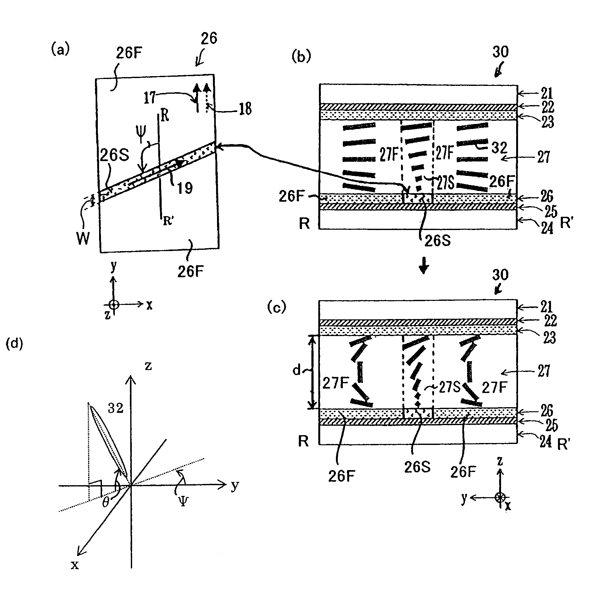
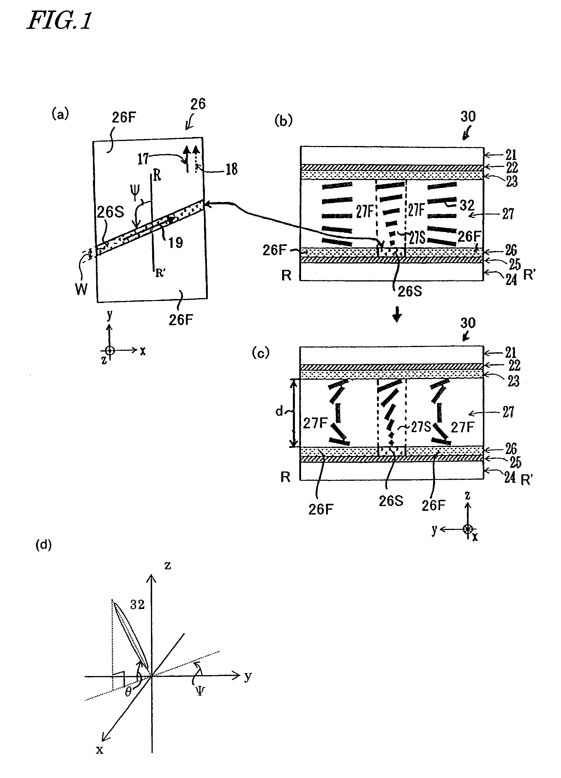
[0014]A liquid crystal display device according to the present invention includes a pair of substrates, a liquid crystal layer placed between the pair of substrates and an alignment film placed on the side of at least one of the pair of substrates facing the liquid crystal layer, wherein the liquid crystal layer has a first region in which the pretilt direction of liquid crystal molecules of which the alignment is regulated with alignment regulating force of a surface of the alignment film is a first direction and a second region in which the pretilt direction is a second direction different from the first direction, and display is performed using bend alignment of the first region of the liquid crystal layer. In such a liquid crystal display device, the second region of the liquid crystal layer acts as the nucleus for splay-bend transition of the first region when a voltage equal to or higher than a splay-bend critical voltage (Vcr) is applied across the liquid crystal layer, and this enables high-speed, reliable bend transition in the first region.

Problems solved by technology

The hardest challenges to the spread of LCD-TVs are said to be the high-speed response characteristic capable of responding to moving images and the wide viewing angle characteristic independent of the angle at which an image is viewed.
As of today, however, no decisive solutions have yet been found.
The OCB mode however has a very troublesome problem that initial transition from splay alignment to bend alignment is necessary before the device is driven.
However, the transition to bend alignment (bend transition) brought by spacers, flaws, alignment disturbance and the like as described above largely depends on the probability, and therefore lacks in reliability and is poor in reproducibility.
This considerably limits the kind of usable alignment film material.
Also, if the method limits the usable liquid crystal material and alignment film material for formation of bend transition nuclei, it is not recommendable to adopt such a method from the standpoint of the fabrication process.
However, in the method described above, a large amount of a chiral agent must be added to attain the π-twist alignment as the initial alignment.

Method used


Image

  • Liquid crystal display device comprising a TN alignment region continuously connectable with a bend alignment region, each region having a different pretilt direction and the method of fabricating the same
  • Liquid crystal display device comprising a TN alignment region continuously connectable with a bend alignment region, each region having a different pretilt direction and the method of fabricating the same
  • Liquid crystal display device comprising a TN alignment region continuously connectable with a bend alignment region, each region having a different pretilt direction and the method of fabricating the same

Examples


embodiment 1

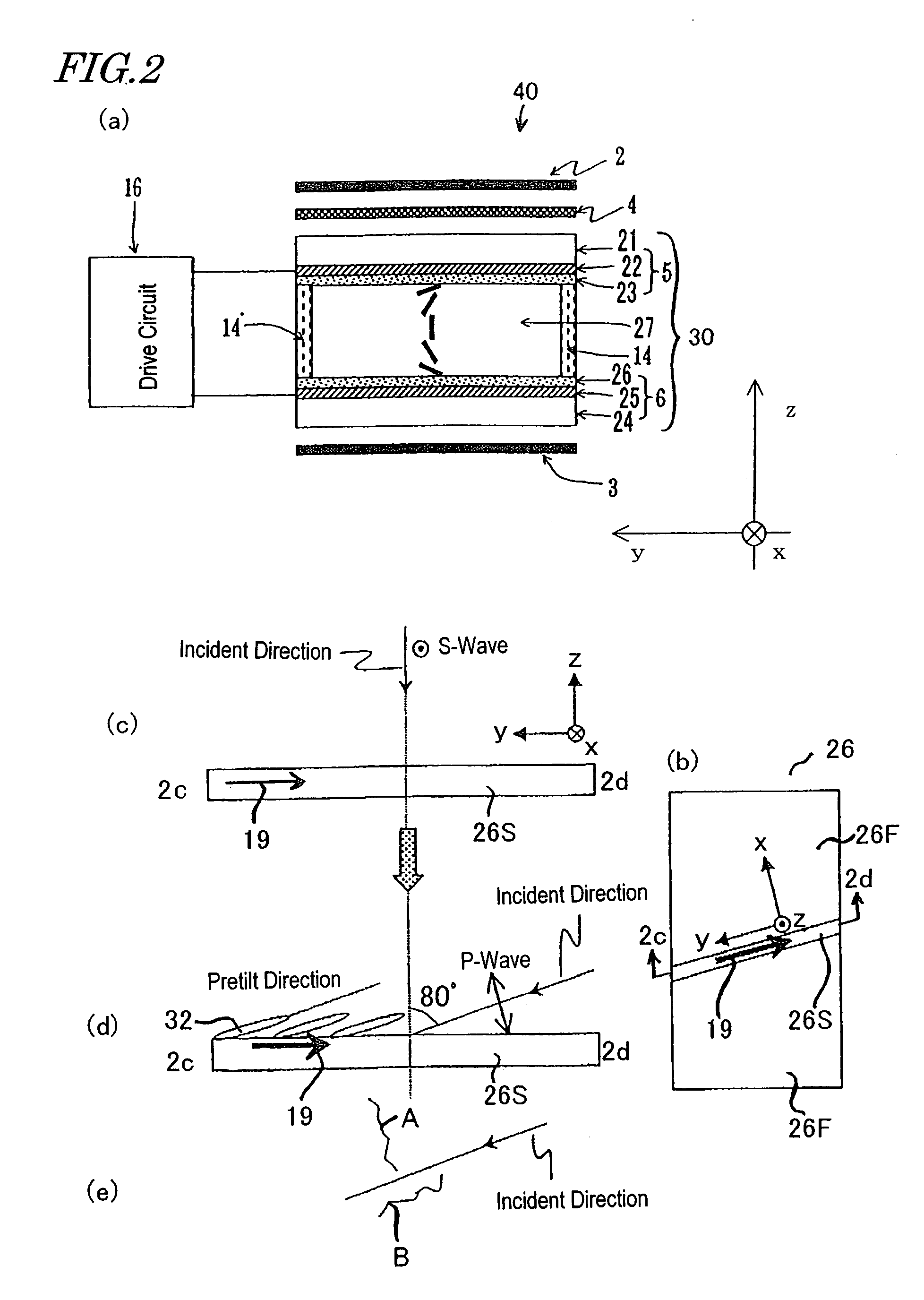
[0073]The liquid crystal display device of the present invention is an OCB mode liquid crystal display device that uses bend alignment of liquid crystal molecules for display and can preferably attain both the high-speed response characteristic and the wide viewing angle characteristic. As shown in FIG. 2(a), a liquid crystal display device 40 of an embodiment of the present invention includes a pair of polarizing plates (polarizers) 2 and 3, a liquid crystal element 30 interposed between the polarizing plates, an optical phase element 4 interposed between the polarizing plate 2 and the liquid crystal element 30, and a drive circuit 16 for driving the liquid crystal element 30. The liquid crystal element 30 includes a pair of electrode substrates 5 and 6 bonded together with seal resin 14 and a liquid crystal layer 27 formed in the space surrounded by the pair of electrode substrates 5 and 6 and the seal resin 14.

[0074]The electrode substrate 5 includes a substrate (transparent subs...

example 1

[0100]Liquid crystal display devices of Example 1 have substantially the same structure as the liquid crystal display device 40 of the embodiment described above with reference to FIGS. 1 and 2(a) and are prepared in substantially the same manner as that in the embodiment. In Example 1, the rubbing direction of the second alignment region 26S (region discontinuous in rubbing direction) of the alignment film 26 on the lower substrate 24 was changed variously to prepare a plurality of liquid crystal display devices.

[0101]Specifically, five liquid crystal display devices (samples #11 to #15) shown in Table 1 below were prepared by varying the angle ψ formed between the first rubbing direction (direction of arrows 17 and 18 in FIG. 1(a)) and the second rubbing direction (direction of arrow 19) of the alignment film 26 in the range of 30° to 150° inclusive. The second alignment film region 26S is in the shape of a stripe extending in the rubbing direction of the second alignment film reg...

example 2

[0117]In Example 2, the amount of the chiral agent added to the liquid crystal layer was changed variously, to prepare liquid crystal display devices similar to the liquid crystal display device 40 of the embodiment described above in much the same manner as that in the above embodiment. Specifically, prepared were four liquid crystal display devices (samples #31 to #34) having values of the ratio of the thickness d of the liquid crystal layer of the liquid crystal element 30 to the natural chiral pitch p of the chiral agent-added liquid crystal layer shown in Table 3 below. The values of d / p of the samples of Example 2 are set to fall within the range between 0 and less than 0.50.

[0118]In the liquid crystal elements in Example 2, the second alignment film region 26S is provided only for the alignment film 26 on the lower substrate 24. Also, the angle ψ formed between the rubbing direction 19 of the second alignment film region 26S and the rubbing direction 17 of the first alignment...


PUM

PropertyMeasurementUnit
angleaaaaaaaaaa
angleaaaaaaaaaa
voltageaaaaaaaaaa

Abstract

The liquid crystal display device of the present invention includes a pair of substrates, a liquid crystal layer placed between the pair of substrates and an alignment film placed on the side of at least one of the pair of substrates facing the liquid crystal layer. The liquid crystal layer has a first region in which the pretilt direction of liquid crystal molecules of which the alignment is regulated with alignment regulating force of a surface of the alignment film is a first direction and a second region in which the pretilt direction is a second direction different from the first direction. Display is performed using bend alignment of the first region of the liquid crystal layer.

Description

BACKGROUND OF THE INVENTION[0001]1. Field of the Invention[0002]The present invention relates to a liquid crystal display device, and more particularly, to a liquid crystal display device suitably used for portable information equipment, notebook PCs, desktop monitors, television sets and the like, which require moving image display characteristics.[0003]2. Description of the Related Art[0004]Conventionally, liquid crystal display devices using a nematic liquid crystal material have been widely used as digit segment displays for watches, calculators and the like. In recent years, making full use of advantages of saving the space and consuming low power, liquid crystal display devices have come into wide use as displays for notebook PCs and desktop monitors. In particular, in the market of desktop monitors, it is no exaggeration to state that conventional CRT monitors have been increasingly replaced with LCD monitors. This trend has also spread to the market of TV monitors in which C...

Claims


Application Information

Patent Timeline
Patent Type & Authority Patents(United States)
IPC IPC(8): G02F1/1337C09K19/02G02F1/141G02F1/139
CPCG02F1/133753G02F1/1395G02F2001/133757G02F1/133757G02F1/139
Inventor INOUE, IICHIROUCHIDA, TATSUO
Owner SHARP KK
Learn More