Super-regenerative receiver including phase-locked loop

a phase-locked loop and receiver technology, applied in the field of electronic circuits, can solve the problems of limiting the usability of such approaches, affecting the reliability of super-regenerative receivers, and affecting the reliability of super-regenerative receivers, and achieve the effect of increasing power consumption

Active Publication Date: 2007-05-08
SADOWSKI BOGDAN
View PDF7 Cites 39 Cited by
  • Summary
  • Abstract
  • Description
  • Claims
  • Application Information

AI Technical Summary

Benefits of technology

[0008](d) to provide the circuit (and method) stabilizing operating frequency of the super-regenerative receiver which is applicable to

Problems solved by technology

Frequency instability is well known disadvantage of super-regenerative receiver.
That is not desired in certain applications, where power consumption is of concern, and thus it limits the usability of such approach.
Addition of the frequency divider, the sequential phase comparator and the charge pump increases complexity, size and cos

Method used


Image

  • Super-regenerative receiver including phase-locked loop
  • Super-regenerative receiver including phase-locked loop
  • Super-regenerative receiver including phase-locked loop

Examples


Embodiment Construction

[0128]Preferred embodiments of the present invention will now be described in details, with reference to the accompanying drawings. This invention may, however, be embodied in many different forms and should not be construed as limited to the embodiments set forth herein. Rather, these embodiments are provided so that the disclosure will be thorough and complete, and will fully convey the scope of the invention to those skilled in the art.

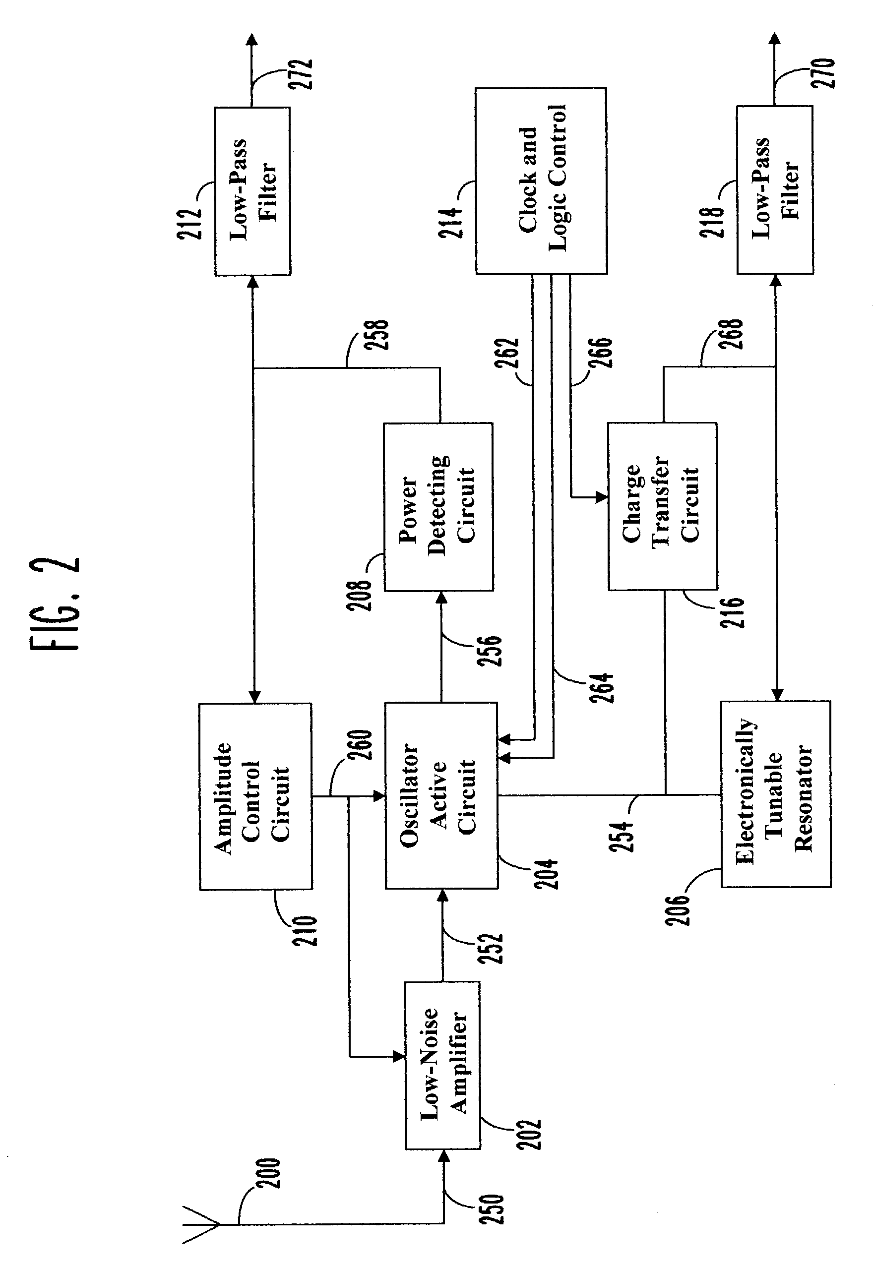
[0129]Referring now to FIG. 2, preferred embodiment of the super-regenerative receiver, according to the invention, includes an electronically tunable resonator 206 which is responsive to resonator signal 254 and frequency control signal 268. The configuration of the electronically tunable resonator 206 is such as the resonator can be represented by equivalent series resonant circuit (therefore the resonator may include phasing transmission line to move the impedance reference plane). Actual implementation of the electronically tunable resonator 20...


PUM


Abstract

An improved low-cost super-regenerative receiver includes sampling phase-locked loop. Phase sampling is controlled by the quench signal (264). In the preferred embodiment, logic state HIGH to logic state LOW transition of the quench signal (264) defines the timing for the event of sampling. While the quench signal (264) is in logic state HIGH, a quenched oscillator is being turned ON and the oscillation amplitude builds-up until a steady-state level is reached. When the oscillator is turned OFF, effective quality factor of an electronically tunable resonator (206) is reduced, by increasing losses in the circuit, thus to ensure aperiodic (non-oscillatory) decay. The resonator's charge—an energy stored on internal reactive components of the resonator (206), which existed at the instant of turning the oscillations OFF, is transferred during precisely defined period of time to the charge holding capacitor (404) of a charge transfer circuit (216). Charge is stored on the charge holding capacitor (404), which is also part of a loop filter, until the described here charge transfer cycle is repeated again. A frequency control signal (268) at the output of the loop filter sets the frequency of the oscillation for the duration of the succeeding oscillator ON time.

Description

FIELD OF THE INVENTION[0001]This invention relates to electronic circuits, and more particularly to super-regenerative radio receivers.BACKGROUND OF THE INVENTION[0002]Super-regenerative receivers are widely used in variety of applications including low-power short-range RF links. Such applications require low-cost receiver with extremely low power consumption. Super-regenerative receiver is suitable for such applications due to its simplicity and relatively good sensitivity. Frequency instability is well known disadvantage of super-regenerative receiver. Therefore, phase-locked loop has been suggested as a means for precise frequency stabilization. One such super-regenerative receiver design is described in Norbert Joehl, et al. “A Low-Power 1-GHz Super-Regenerative Transceiver with Time-Shared PLL Control” IEEE Journal of Solid-State Circuits, vol. 36, No.7, July 2001, which is incorporated here by reference. At least three additional blocks are required (ECL frequency divider, se...

Claims


Application Information

Patent Timeline
IPC IPC(8): H04B1/10H03D11/02H03D11/06H04B1/30
CPCH03D11/02H03D11/06H04B1/30
Inventor SADOWSKI, BOGDAN
Owner SADOWSKI BOGDAN
Why Eureka
Try Eureka