Clutch for rotary power tool and rotary power tool incorporating such clutch

a technology of rotary power tools and clutches, which is applied in the direction of clutches, slip couplings, and percussive tools. it can solve the problems of overload clutches slipping, hammer housings prone to rotate against the grip of users, and increase torque transmitted via the rotary drive train, so as to reduce the tendency of the first clutch member

Active Publication Date: 2007-05-15
BLACK & DECKER INC
View PDF35 Cites 38 Cited by
  • Summary
  • Abstract
  • Description
  • Claims
  • Application Information

AI Technical Summary

Benefits of technology

[0011]second biasing means adapted to act between said first and second clutch members for urging said second clutch member towards said first condition. By providing a first clutch member having at least one first friction surface inclined relative to the first axis for engaging a respective corresponding second friction surface on the spindle, this provides the advantage of providing a reaction force, from the or each corresponding second friction surface on the spindle, which has a component resisting axial movement of the first clutch member relative to the spindle. This in turn reduces the tendency of the first clutch member to move axially too rapidly relative to the spindle.
[0012]In a preferred embodiment, said second clutch member is adapted to be mounted to said first clutch member and to slide relative thereto in a direction substantially parallel to said first axis, said first and second clutch members have cooperating engaging portions, and said second biasing means is adapted to urge said cooperating engaging portions into engagement with each other, such that when a torque applied between said first and second clutch members does not exceed a predetermined value, said cooperating engaging portions engage each other to prevent relative rotation between said first and second clutch members, and when said torque exceeds said predetermined value, axial movement of said second clutch member relative to said first clutch member against the action of said second biasing means occurs to disengage said cooperating engaging portions from each other, thereby permitting relative rotation between said first and second clutch members.

Problems solved by technology

During rotary hammering or drilling, when working on materials of non-uniform hardness, for example aggregate or steel reinforced concrete, the bit can become stuck, which causes the torque transmitted via the rotary drive train to increase and causes the hammer housing to tend to rotate against the grip of the user.
An overload clutch can slip and interrupt rotary drive to the bit at a torque threshold below that where a user may experience difficulty in controlling the hammer.
When a predetermined threshold torque is exceeded, for example as a result of the drill bit becoming stuck in a workpiece, the ratchet plates can slip relative to each other against the action of the spring.
However, known overload clutches of this type suffer from the drawback that at very high torque levels, the ratchet plates can be moved rapidly out of engagement with each other to the extremities of their permitted relative movement and then move rapidly back into engagement with each other, causing problems in controlling the tool.

Method used


Image

  • Clutch for rotary power tool and rotary power tool incorporating such clutch
  • Clutch for rotary power tool and rotary power tool incorporating such clutch
  • Clutch for rotary power tool and rotary power tool incorporating such clutch

Examples


Embodiment Construction

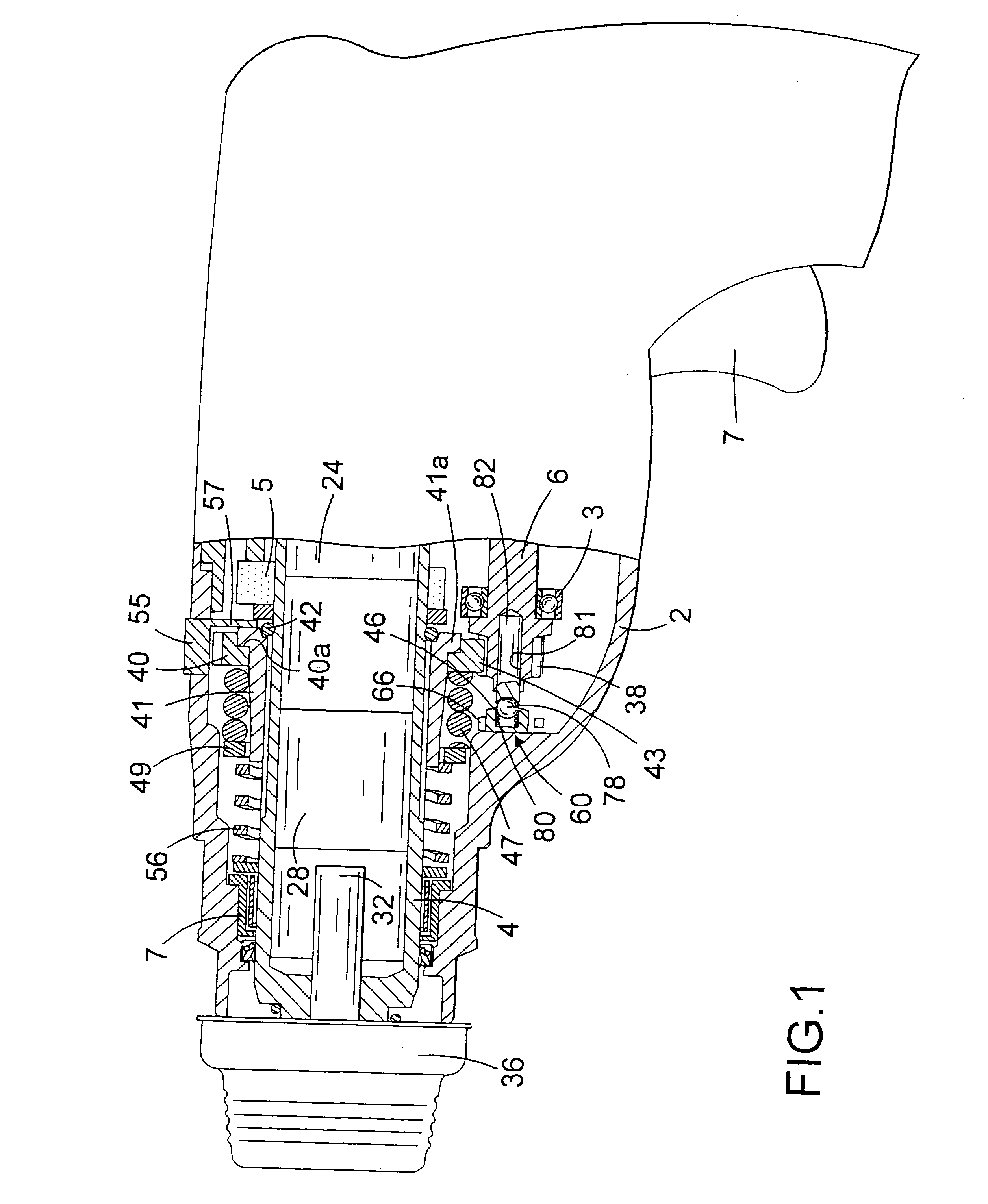
[0060]Referring to FIG. 1, a rotary hammer has a forward portion shown in cross-section, and a rear portion incorporating a motor and pistol grip rear handle in a conventional manner. Alternatively, the handle may be of the D handle type. The handle portion incorporates a trigger switch 7 for actuating an electric motor which carries a pinion (not shown) at the forward end of its armature shaft. The pinion of the motor rotatingly drives an intermediate shaft 6 via a gear which is press fit onto the rearward end of the intermediate shaft 6. The intermediate shaft 6 is rotatably mounted in a housing 2 of the hammer via a first bearing (not shown) located at the rearward end of the intermediate shaft 6 and a forward bearing 3 located at the forward end of the intermediate shaft 6.

[0061]A wobble drive hammering mechanism, of a type which will be familiar to persons skilled in the art, is provided for reciprocatingly driving a piston 24. The piston 24 is slidably located within a hollow ...


PUM


Abstract

An external surface of a spindle is formed with tapering grooves which become narrower in a direction towards the forward end of the spindle. A slider sleeve is provided with splines which also taper in a forward direction. In this way, the slider sleeve is prevented from rotating relative to the spindle, but can slide axially. A rearward end of the slider sleeve includes a recess containing an elastomeric O-ring. When the drive torque exceeds a predetermined threshold, inclined surfaces of the mutually engaging teeth on the spindle drive gear and slider sleeve slide over each other, as a result of which the drive gear slides forwardly along the slider sleeve against the action of a spring. The spindle drive gear can then rotate relative to the slider sleeve and the cooperating sets of teeth ratchet over each other, preventing spindle drive gear being from rotating the spindle.

Description

FIELD OF THE INVENTION[0001]The present invention relates to a clutch for a rotary power tool, and relates particularly, but not exclusively, to an overload clutch for a handheld power hammer. The invention also relates to a handheld power hammer incorporating such a clutch.BACKGROUND OF THE INVENTION[0002]Rotary hammers are known which have a housing and a hollow cylindrical spindle mounted in the housing. The spindle allows insertion of the shank of a tool or bit, for example a drill bit or a chisel bit, into the front end thereof so that it is retained in the front end of the spindle with a degree of axial movement. The spindle may be a single cylindrical part or may be made of two or more cylindrical parts, which together form the hammer spindle. For example, a front part of the spindle may be formed as a separate tool holder body for retaining the tool or bit. Such hammers are generally provided with an impact mechanism which converts the rotational drive from an electric motor...

Claims


Application Information

Patent Timeline
Patent Type & Authority Patents(United States)
IPC IPC(8): B25D16/00B25D17/08
CPCB25D16/003B25D2250/165B25D2250/231B25D2250/345
Inventor DROSTE, MANFRED
Owner BLACK & DECKER INC
Why Eureka
Try Eureka