Emergency pitch drive power supply

a power supply and emergency technology, applied in the direction of electric generator control, machines/engines, mechanical equipment, etc., can solve the problems of unnecessary provision of batteries as energy storage in emergency cases, and achieve the effect of improving the usability of such a wind turbine, reducing time and costs, and improving the usability

Inactive Publication Date: 2007-05-15
GENERAL ELECTRIC CO
View PDF9 Cites 114 Cited by
  • Summary
  • Abstract
  • Description
  • Claims
  • Application Information

AI Technical Summary

Benefits of technology

[0011]Thus, the wind turbine is adapted to pitch its rotor blades into a feathered position even when no external power is available, e.g. in case of a complete grid failure. Furthermore, the maintenance effort, i.e. time and costs, are considerably reduced compared to a battery backup system. This improves the usability of such a wind turbine for remote locations, e.g. off-shore sites. Finally, the backup generator system is more robust compared to the battery backup system so that a wind turbine employing such an auxiliary generator is better adapted for harsh environmental conditions, e.g. off-shore conditions.

Problems solved by technology

Thus, the provision of batteries as energy storage for emergency cases is rendered unnecessary.
Finally, such an emergency pitch drive power supply is more reliable than a battery-based power supply which is an extremely important issue for fallback systems.

Method used


Image

  • Emergency pitch drive power supply
  • Emergency pitch drive power supply
  • Emergency pitch drive power supply

Examples


Embodiment Construction

[0027]Reference will now be made in detail to the various embodiments of the invention, one or more examples of which are illustrated in the figures. Each example is provided by way of explanation of the invention, and is not meant as a limitation of the invention. For example, features illustrated or described as part of one embodiment can be used on or in conjunction with other embodiments to yield yet a further embodiment. It is intended that the present invention includes such modifications and variations.

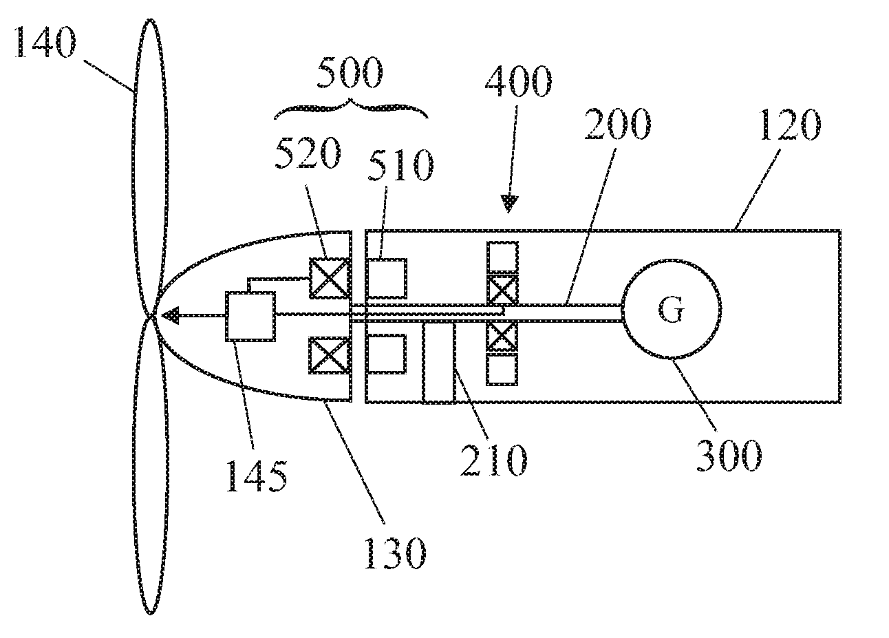
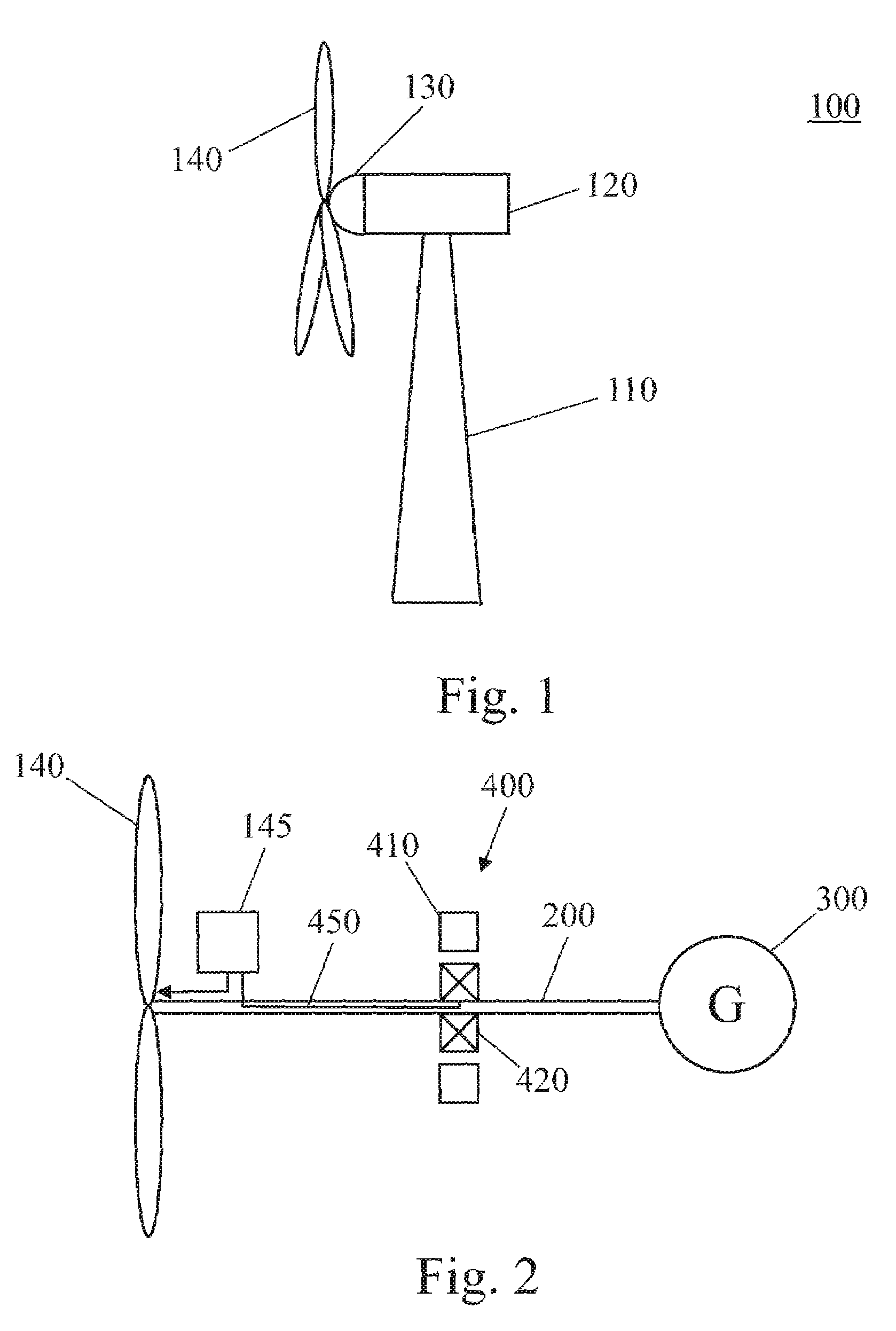
[0028]FIG. 1 is a schematic view of a wind turbine. The wind turbine 100 includes a tower 110 to which a machine nacelle 120 is mounted at its top end. The nacelle houses a drive train to which a main electric generator is connected. A hub 130 bearing three rotor blades 140 is mounted to a lateral end of the machine nacelle 120. The rotor blades 140 can be adjusted by pitch drives which are typically accommodated inside hub 130.

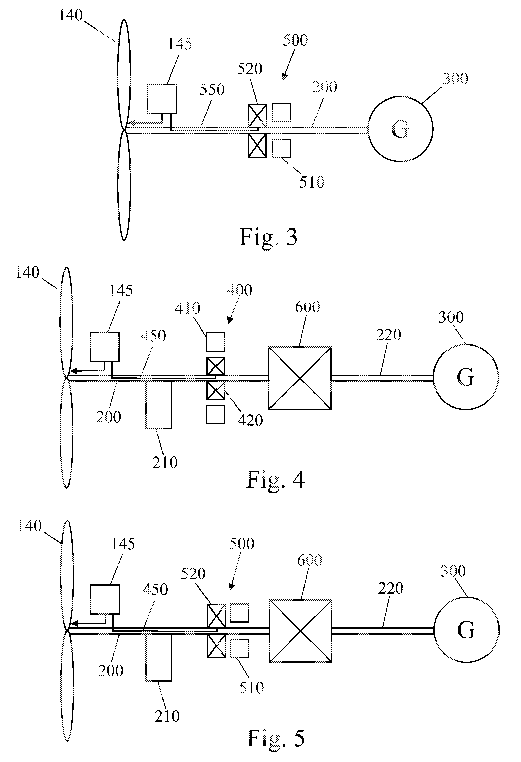
[0029]FIG. 2 is a block diagram of an emergency po...


PUM


Abstract

An emergency pitch drive power supply is provided, the emergency pitch drive power supply comprising an auxiliary generator for producing electric power, wherein the auxiliary generator is a permanently excited multi-pole generator adapted to generate sufficient power for a pitch drive of a wind turbine when driven with wind rotor speed, and wherein the auxiliary generator is connected to at least one pitch drive motor of the wind turbine.

Description

FIELD OF THE INVENTION[0001]The present invention relates to an emergency pitch drive power supply for wind turbines.BACKGROUND OF THE INVENTION[0002]Typically, modern wind turbines have rotor blades with adjustable pitch angle. The rotor blades can be rotated about their longitudinal axis by means of a pitch drive disposed in the rotor hub. Typically, the pitch drive is actuated electrically or hydraulically. By adjusting the pitch angles of the rotor blades, the power generation of the wind turbine can be controlled as well as an aerodynamical braking of the rotor can be accomplished. Particularly, the rotor blades generate a braking torque when moved into feather position. Thereby, the rotor blades ensure that the rotor is not further accelerated and, thus, the rotor blades form an aerodynamical brake for the wind turbine.[0003]The aerodynamical brake effect of the rotor blades is also used for braking the rotor in case of emergency, e.g. when a failure of the drive system occurs...

Claims


Application Information

Patent Timeline
Patent Type & Authority Patents(United States)
IPC IPC(8): F03D9/00
CPCF03D7/0224F03D7/0244F03D7/0264F03D9/002F03D11/0058F03D11/0075F05B2220/7062F05B2220/70642F05B2220/7068F05B2260/76F05B2260/901F05B2270/1011F05B2270/107Y02E10/723Y02E10/725Y02E10/722F03D9/25F03D15/20F03D80/82F03D80/88Y02E10/72
Inventor EDENFELD, THOMAS
Owner GENERAL ELECTRIC CO
Why Eureka
Try Eureka