Optical module, and multi-core optical collimator and lens housing therefor

a technology of optical collimators and lenses, applied in the field of optical modules, can solve the problems of easy difficult to always apply a minute amount of adhesive to the lens, and mechanical damage to the fiber end faces, etc., to prevent deterioration of light sources, increase insertion loss, and facilitate separation

Inactive Publication Date: 2007-05-15
FURUKAWA ELECTRIC CO LTD
View PDF7 Cites 68 Cited by
  • Summary
  • Abstract
  • Description
  • Claims
  • Application Information

AI Technical Summary

Benefits of technology

[0024]Still another object of the present invention is to provide an optical module capable of reducing insertion loss in connecting multi-core collimators.
[0037]According to still another aspect of the present invention, there is provided an optical module in which first and second optical fiber housings that individually receive end portions of optical fibers and first and second lens housings that are disposed between the first and second optical fiber housings and individually receive lenses are positioned by means of guide pins. This optical module comprises an optical function component disposed between the first and second lens housings, and at least one of inner end faces of the first and second lens housings is formed with three support points that abut against an end face of the optical function component, whereby the optical function component is stably held between the lens housings, thus improving optical coupling efficiency.

Problems solved by technology

Besides, the exposed end faces of the multi-core optical fibers can be in contact with each other during operation of connecting the two optical connectors, causing mechanical damages to the fiber end faces.
In the module 1 using adhesive to fix the lens 5 to the lens housing 3, an error in lens position tends to occur since it is extremely difficult to always constantly apply a minute amount of adhesive to the lens 5 which is extremely small in size.
As a result, an applied amount of adhesive varies between lenses 5, causing variations in shrinkage of adhesive and in lens position.
Besides, the optical module 1 does not permit the lens position to change after the lens 5 being fixed.
Thus, the dislocated lens position caused by an error in applied amount of adhesive results in inaccuracy of focal distance S and lens-to-lens distance D, producing a large optical coupling loss.
This results in an increased number of assembling man-hours to increase assembling costs.
As a result, the focal distance S and the lens-to-lens distance D become unstable between individual optical modules, producing a large variation in their optical coupling characteristics.
Besides, the unstable positional relation between optical module components, such as between the lens 5 and the optical fiber 4, can produce a positional deviation that causes a large insertion loss.
In particular, when impact is applied to the optical module 1, the lens-to-lens distance D and the focal distance S greatly deviate from design values, causing a large coupling loss and a large insertion loss.
In a case where the optical function component is fixedly positioned by means of the entire end faces of the two lens housings, there is a fear that a desired optical coupling efficiency cannot be attained for the reason that it is practically difficult to machine the entire end face of the lens housing flat enough to attain the desired coupling efficiency from the viewpoints of machining accuracy and machining cost.
Accordingly, with such an arrangement having an optical function component positioned by means of the entire end faces of lens housings that are not completely flat, it is difficult to always position the optical function component at the same position with the same angle.
In other words, the position and angle of the positioned optical function component vary between individual optical modules, and hence it is quite difficult to stably manufacture optical modules having a desired optical coupling efficiency.

Method used


Image

  • Optical module, and multi-core optical collimator and lens housing therefor
  • Optical module, and multi-core optical collimator and lens housing therefor
  • Optical module, and multi-core optical collimator and lens housing therefor

Examples


first embodiment

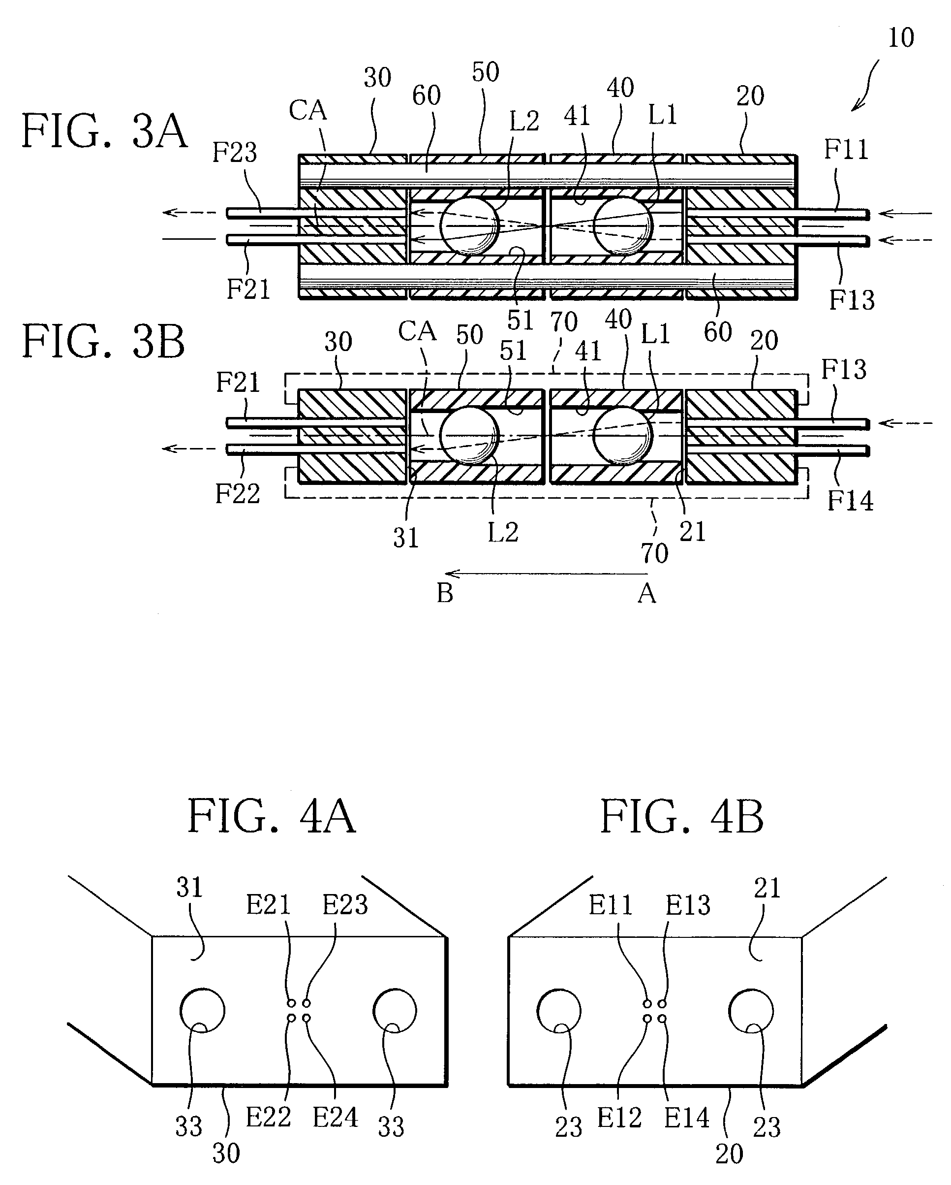
[0129]With reference to FIGS. 3–5, an optical module according to the present invention will be explained in detail.

[0130]This optical module 10 comprises a first fiber unit 20 in which distal end portions of two pairs of optical fibers F11–F14 are fixedly arranged in parallel to the longitudinal direction (AB direction) of the optical module 10; a second fiber unit 30 in which distal end portions of two pair of optical fibers 21–24 are fixedly arranged in parallel to the AB direction; a first collimator unit 40 having a lens Ls for collimating outgoing light beams from the optical fibers F11–F14 of the first fiber unit 20; a second collimator unit 50 having a lens L2 for collimating outgoing light beams from the optical fibers F21–24 of the second fiber unit 30; a pair of guide pins 60 for positioning the units 20, 30, 40 and 50 to one another; clips 70 for fixedly holding these units 20, 30, 40 and 50. The first fiber unit 20 and the first collimator unit40 constitute a first mult...

third embodiment

[0153]In the following, an optical module will be explained.

[0154]As shown in FIG. 9, this optical module 210 comprises a first ferrule 220 serving as a fiber unit in which two pairs of optical fibers F11–F14 (FIG. 11) are fixed in parallel to the optical axis; a second ferrule 230 serving as another fiber unit in which two pairs of optical fibers F21–F24 (FIG. 11) are fixed in parallel to the optical axis; a first lens section 240 having a first lens L1 for collimating outgoing light beams from the optical fibers F11–F14 of the first ferrule 220; a second lens section 250 having a second lens for collimating outgoing light beams from the optical fibers F21–F24 of the second ferrule 230; a holder 280, disposed between the first and second lens sections 240, 250, for holding a band pass filter 282; and a casing 260 for receiving the elements 220, 230, 240, 250 and 280. The first ferrule 220 and the first lens section 240 constitute a first multi-core collimator, whereas the second f...

fourth embodiment

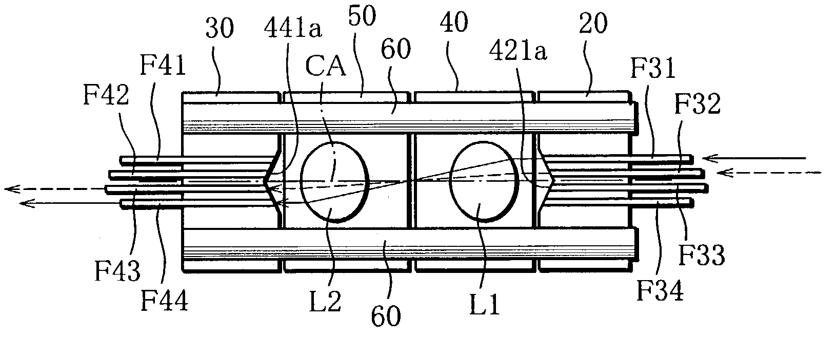
[0168]Next, with reference to FIGS. 14A and 14B, an operation of the optical module will be explained.

[0169]In a case where a mirror 81 is not inserted between collimator units 40, 50 as shown in FIG. 14A, a laser light beam from an outer optical fiber F31 in the first fiber unit 20 is coupled to an outer optical fiber F44 in the second fiber unit 30, which fiber is disposed diametrically opposite the optical fiber F31, whereas a laser light beam from an inner optical fiber F32 is coupled to an inner optical fiber F43 disposed diametrically opposite the optical fiber F32. The laser light beams from the optical fibers F31, F32 are accurately collimated through the first lens L1, cross the center axis CA, and are accurately focused to end faces of optical fibers F44, F43 through the second lens L2. On the other hand, in a case where the mirror 81 is inserted between the collimator units 40, 50 as shown in FIG. 14B, a laser light beam from the outer optical fiber F31 of the first fibe...


PUM


Abstract

An optical module includes first and second fiber units that hold end portions of first and second optical fibers, and first and second collimators disposed between these fiber units and having first and second lenses, respectively. End faces of the first and second optical fibers are disposed on imaginary circumferences on the end faces of the first and second fiber units. Laser light beams from the end face of the first optical fiber are collimated by the first lens and then focused by the second lens, and enter the end face of the second optical fiber that is disposed diametrically opposite to the first optical fiber with respect to the center axis of the optical module.

Description

BACKGROUND OF THE INVENTION[0001]1. Technical Field[0002]The present invention relates to an optical module for use in the field of optical communication and optical measurement, and more particularly, to an optical module for connecting optical fibers so as to realize functions of optical switch, optical branching, optical coupling, etc., and relates to an optical collimator and a lens housing that are used to constitute such an optical module.[0003]2. Related Art[0004]In optical communication systems and optical measuring systems, a variety of optical connectors and optical modules for connecting optical fibers are utilized. For instance, JP-A-8-114724 discloses an MT (Mechanically Transferable) type optical connector that is adapted to be detachably joined to another optical connector of the same construction by means of guide pins. The two joined optical connectors connect multi-core optical fibers together, which are held by these connectors positioned by the guide pins inserte...

Claims


Application Information

Patent Timeline
Patent Type & Authority Patents(United States)
IPC IPC(8): G02B6/32G02B6/38
CPCG02B6/32G02B6/3885G02B6/322G02B6/327
Inventor SHIGENAGA, TAKASHISUEMATSU, KATSUKIMATSUURA, HIROSHIYUGUCHI, RENICHISHIGEMATSU, TAKASHI
Owner FURUKAWA ELECTRIC CO LTD
Why Eureka
Try Eureka