Continuous closed-loop power control system including modulation injection in a wireless transceiver power amplifier

a power amplifier and closed-loop technology, applied in power management, low noise amplifiers, wireless communication, etc., can solve the problems of consuming significantly more power, inefficient highly linear power amplifiers, and inability to adapt existing gsm modulation schemes to transmit signals

Inactive Publication Date: 2007-05-15
XUESHAN TECH INC
View PDF23 Cites 22 Cited by
  • Summary
  • Abstract
  • Description
  • Claims
  • Application Information

AI Technical Summary

Benefits of technology

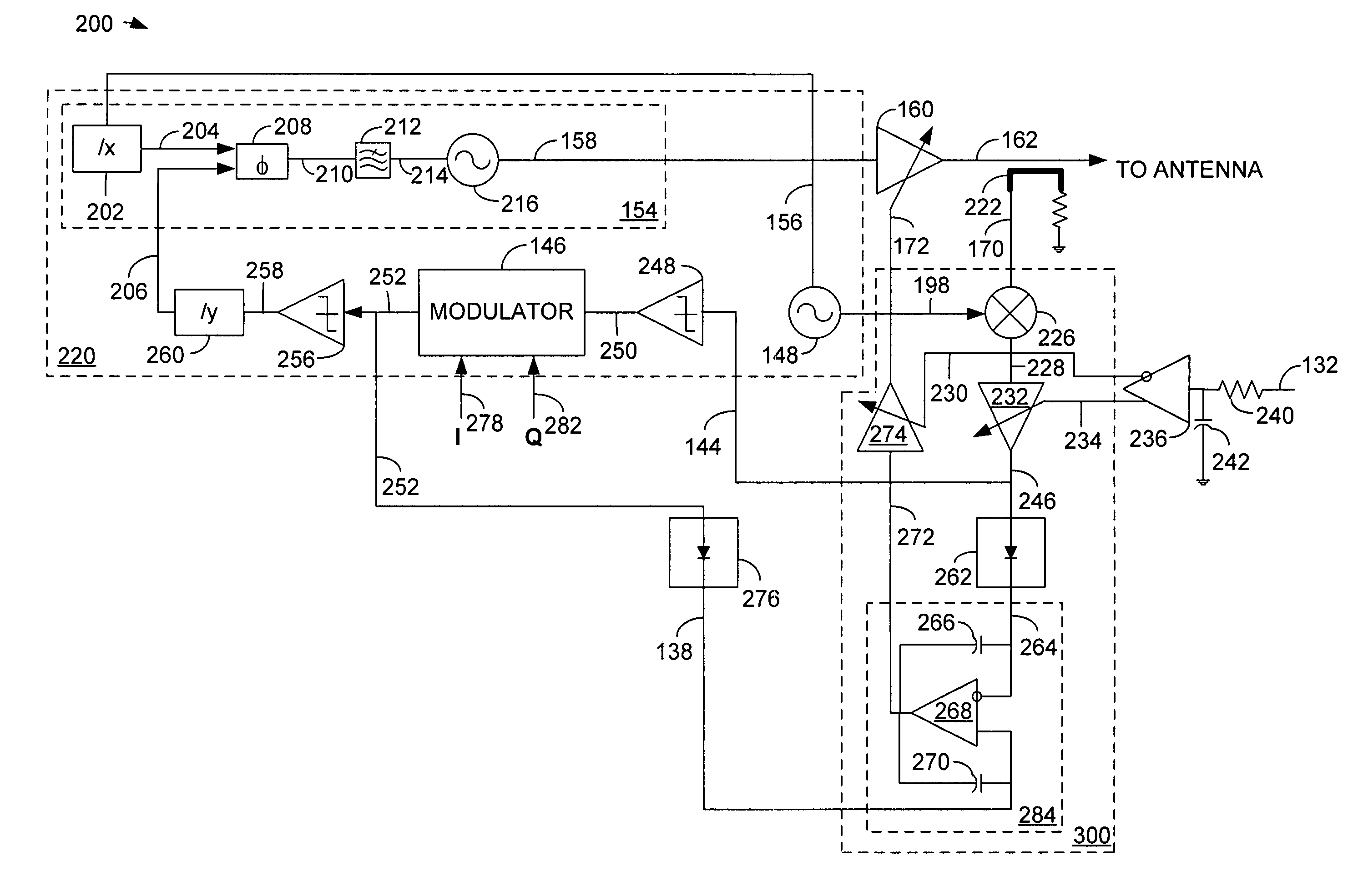
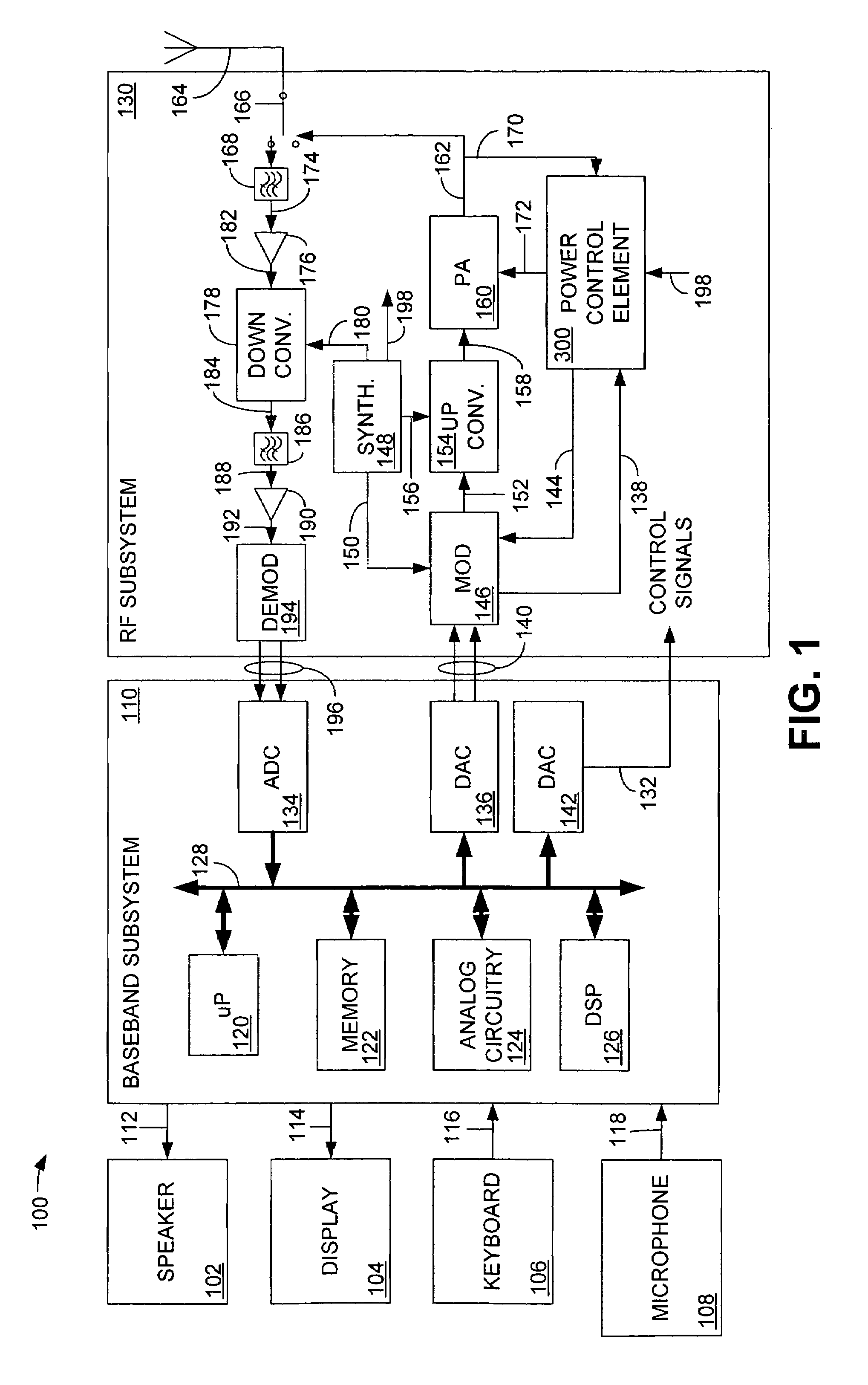
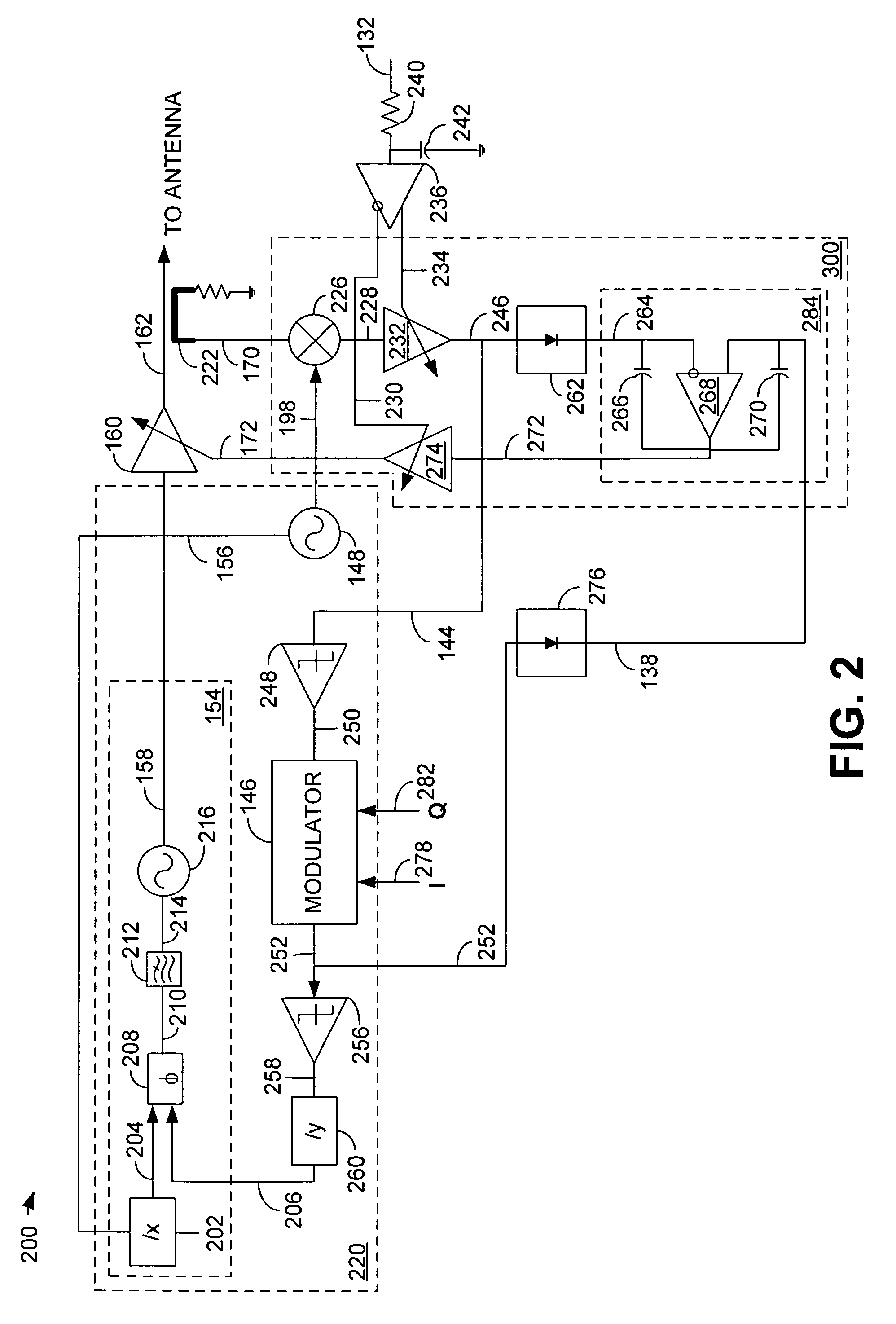
[0015]The invention provides a continuous closed-loop power control system, which includes modulation injection into a wireless transceiver's power amplifier that allows the use of non-linear, power efficient amplifiers. The invention uses a single continuous closed-loop power control system that allows an AM signal to be injected into the power amplifier through the power amplifier control port. The AM signal is derived from the output of an I / Q modulator and supplied to a comparator located within the power control feedback loop. By using the leakage from the power amplifier as feedback to a translation loop during the initial power amplifier ramp-up, continuous phase feedback to the translation loop is achieved during the entire power amplification ramp-up period, thus eliminating the need for multiple feedback loops.

Problems solved by technology

Unfortunately, existing GSM modulation schemes are not easily adapted to transmit a signal that includes both a PM component and an AM component.
Unfortunately, highly linear power amplifiers are very inefficient, thus consuming significantly more power than a non-linear power amplifier and drastically reducing the life of the battery or other power source.
This condition is further complicated because transmitters typically employed in GSM communication systems transmit in bursts and must be able to control the ramp-up of the transmit power as well as have a high degree of control over the output power level over a wide power range.
Unfortunately, this requires the use of a highly linear, and therefore very inefficient, power amplifier.
Unfortunately, these methods are costly and inefficient.
These architectures are complex, unreliable, require periodic calibration, and cannot support multiple transmission standards without significant adjustments to the supporting analog and digital circuitry.
Further, in those transmission standards in which both a PM signal and an AM signal are sent to a power amplifier, unless the power amplifier is very linear, it may distort the combined transmission signal by causing undesirable AM to PM conversion.
This conversion is detrimental to the transmit signal and can require the use of a costly and inefficient linear power amplifier.

Method used


Image

  • Continuous closed-loop power control system including modulation injection in a wireless transceiver power amplifier
  • Continuous closed-loop power control system including modulation injection in a wireless transceiver power amplifier
  • Continuous closed-loop power control system including modulation injection in a wireless transceiver power amplifier

Examples


embodiment 400

[0053]FIG. 4 is a schematic view illustrating an alternative embodiment 400 of the power amplifier circuit of FIG. 2. In some applications it may be desirable to have the ability to transmit an AM signal having a very wide bandwidth. Therefore, and in a departure from that discussed above with respect to FIG. 2, the power amplifier circuit 400 of FIG. 4 includes a mixer 492 added to the phase locked loop 420. The mixer 492 receives the output of the TX VCO 416 on connection 494 and also receives as input the output of a low-pass filter 490 via connection 496.

[0054]To develop the signal for input to the mixer 492, the output of modulator 446 on connection 452 is supplied to mixer 480. Mixer 480 combines the PM component of the signal on connection 458 with the AM component of the signal on connection 452. The mixer 480 combines the signal on connection 452 containing the AM and very small PM component and the signal on connection 458 containing the very small PM component, and combin...

embodiment 500

[0057]FIG. 5 is a schematic view illustrating another alternative embodiment 500 of the power amplifier circuit of FIG. 2. The power amplifier circuit 500 includes power control loop 500, where modulator 546 is placed at the output of variable gain element 532. The input signal to modulator 546 on connection 538 is a constant level signal supplied by variable gain element 532. The output of variable gain element 532 includes both an AM and PM component. The baseband I and Q information signals are supplied to the modulator 546 via connections, 578 and 582, respectively.

[0058]With respect to the PM signal on connection 538, when a PM signal is supplied to modulator 546, the I and Q components will remove, or greatly reduce the level of the PM signal on connection 538 within the loop bandwidth of phase locked loop 520. With respect to the AM portion of the signal on connection 538, the I and Q portions will also reduce the AM component by a function equal to the gain of the power cont...


PUM


Abstract

A single continuous closed-loop power control feedback system provides seamless power control for a power amplifier and also enables an AM signal to be injected into the power amplifier through the power amplifiers' control port. The AM signal is developed by an I / Q modulator and supplied to a comparator located in the power control loop. By using leakage from the power amplifier as feedback to a phase locked loop during initial power amplifier power ramp-up, the single continuous closed-loop power control system provides continuous feedback to the phase locked loop during the entire power amplification ramp-up period and eliminates the need for multiple feedback loops.

Description

[0001]This application is a continuation of U.S. patent application Ser. No. 09 / 704,930, filed on Nov. 2, 2000 now U.S. Pat. No. 6,801,784.BACKGROUND OF THE INVENTION[0002]1. Field of the Invention[0003]This invention relates to the versatile transmission of radio frequency power in a wireless communication device transmitter, and more particularly, to a continuous closed-loop power control system including modulation injection into a wireless transceiver's power amplifier.[0004]2. Related Art[0005]With the increasing availability of efficient, low cost electronic modules, mobile communication systems are becoming more and more widespread. For example, there are many variations of communication schemes in which various frequencies, transmission schemes, modulation techniques and communication protocols are used to provide two-way voice and data communications in a handheld telephone like communication handset. The different modulation and transmission schemes each have advantages an...

Claims


Application Information

Patent Timeline
Patent Type & Authority Patents(United States)
IPC IPC(8): H04B7/00H04B1/04H03G3/30H03F1/02H04B7/005
CPCH03F1/0272H04W52/52H03F2200/294H03F2200/372H04B2001/0416H04W52/08
Inventor ROZENBLIT, DMITRIYDAMGAARD, MORTENFAGG, RUSSELL J.DOMINO, WILLIAM J.
Owner XUESHAN TECH INC
Why Eureka
Try Eureka