
Cloth prepreg and wet process for manufacturing the same

a technology of wet process and cloth, applied in the direction of liquid surface applicators, pretreatment surfaces, coatings, etc., can solve the problems of cfrp skin hole, unstable woven fabric, and application only to a limited exten

Inactive Publication Date: 2007-05-22
TORAY IND INC
View PDF27 Cites 8 Cited by
  • Summary
  • Abstract
  • Description
  • Claims
  • Application Information

AI Technical Summary

Benefits of technology

[0012]Preferably the woven fabric has a cover factor of 70% or more, more preferably 90% or more, and preferably comprises yarns substantially free from twist. More preferably, the process comprises the step (A), wherein the number of crossing points is in the range of 2,000 to 70,000/m2, still more preferably 2,500 to 25,000/m2, the cover factor is 90% or more and the warp and weft yarns are substantially free from twist and have a width of 3 to

Problems solved by technology

However, because the carbon fiber is expensive, it can be applied only to a limited extent, even in aircraft where lightweight is most wanted.
However, in the event that a large void exists in the prepreg where carbon fiber does not exist at the place contacting the honeycomb core, such an opening causes a hole in the CFRP skin.
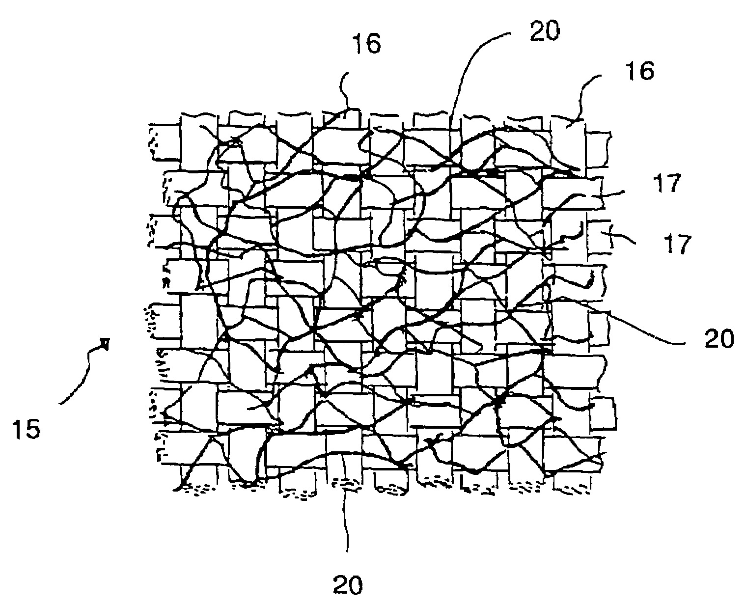
Furthermore, this woven fabric is unstable because the flatness of yarn is easily lost during the drying step employed when a wet process of manufacturing the prepreg (which is otherwise excellent in resin impregnation to the woven fabric) is employed.
However, the flatness was lost during the wet process for manufacturing a prepreg, resulting in a mesh-like woven fabric with a narrow yarn.
Observing how the flatness of yarn is lost during the prepreg process, we found that the flatness of woven yarn can be maintained during impregnation of the resin diluted with a solvent, but a while after the woven fabric enters the drying zone, the flatness gradually begins to be lost.

Method used


Image

  • Cloth prepreg and wet process for manufacturing the same
  • Cloth prepreg and wet process for manufacturing the same
  • Cloth prepreg and wet process for manufacturing the same

Examples


examples

Fabric A

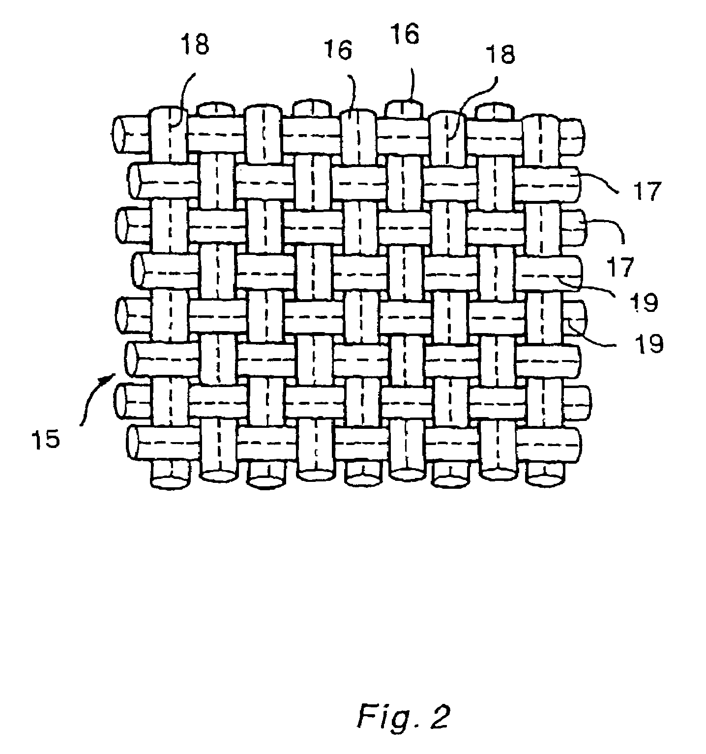
[0086]As a warp, a twist-free flat carbon fiber yarn with a number of filaments of 6,000 was circumferentially taken-out from the bobbin in a manner such as to maintain zero twist and fed to a weaving machine while maintaining the flatness of the yarn in the warp path.

[0087]The weft was, using the same carbon fiber yarn as the warp, axially taken-out in a conventional way to manufacture a fabric A with a weight of carbon fiber of 200 g per square meter, a yarn density of the warp and weft of 2.5 y / cm, and a number of crossing points in a plain weave of 62,500. The number of twists of the warp and weft composing this fabric was measured and found to be zero, whereas the weft had a number of twists of 2.6 times / m in an average of 10 yarns. The parts of the weft in which twists were present were narrow in width, and the weft, unlike the flatness in the warp, became narrow over the entire length and the fabric cover factor was 89%, and the area of the openings of the fabric was ...

examples 1 to 2

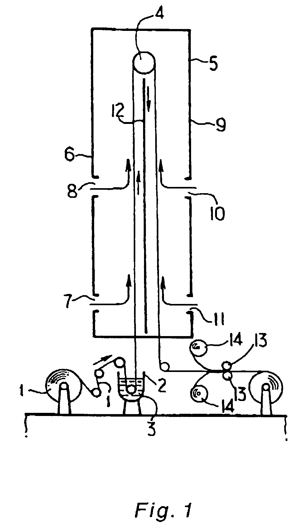
[0090]Methanol was used as phenol resin solvent, and the amount of methanol was controlled so that a prepreg resin weight ratio WR of about 40% at a processing speed of the prepreg of 1.5 m / minute was prepared using the apparatus in FIG. 1.

[0091]The diluted resin was placed in the resin bath 2 set below the vertical drying furnace 5, and into this resin bath 2, a rolled fabric A was dipped by drawing out at a speed of 1.5 m / minute, to impregnate resin in the fibers of the fabric. Fabric was then passed through the vertical drying furnace 5 carrying a roll 4 at the top of the furnace at a height of 10 m from the entrance to the drying furnace 5. The fabric impregnated with diluted resin was drawn up linearly to the roll 4 after passing through the resin baths, and hot air was blown in a lateral direction on to the fabric surface from the side wall 6 facing the travel path of the upwardly moving fabric, thereby drying the solvent to a certain degree, and then reversing the direction o...

example 3 to 11

, Comparative Examples 3 to 5

[0098]Using fabric C with a yarn width of 6.5 mm, a ratio of yarn width to yarn thickness of 65, twist-free and flat, composed of carbon fiber yarn with a number of filaments of 12,000 and a yarn density of the warp and weft of 1.25 y / cm, a number of crossing points in a plain weave of 15,600 per square meter, and a weight of carbon fiber of 200 g per square meter and fabric D with a yarn density of the warp and weft of carbon fiber yarn (the same as the abovementioned reinforcing fiber) of 1.00 y / cm, a number of crossing points of 10,000 per square meter in a plain weave, and a weight of carbon fiber of 160 g per square meter, fixed fabrics with a width of 100 cm were manufactured, by doubling binder yarns located at the center of the yarn width of the warp and / or weft, each of which binder yarns consisted of a sheath yarn of a low melting point nylon copolymer, low melting point polyester or polyethylene compatible with alcohol as a covering binder com...


PUM

PropertyMeasurementUnit
Temperatureaaaaaaaaaa
Fractionaaaaaaaaaa
Shrinkageaaaaaaaaaa

Abstract

A wet process for manufacturing a cloth prepreg with a uniform fiber distribution and large cover factor comprises impregnating a woven fabric with a diluted resin and drying, which fabric has a number of crossing points of warp and weft in the range of 2,000 to 70,000 / m2, which process further comprises at least one of the steps (A) and (B), namely(A) a step of distributing a line-shaped binder on the fabric to fix the yarn flatness prior to impregnating the fabric with a resin diluted with a solvent, at least 80% of which solvent is a nonsolvent of the binder and,(B) a step of calendering the woven fabric after drying.

Description

RELATED APPLICATIONS[0001]This divisional application claims priority from parent application Ser. No. 09 / 079,468, filed May 15, 1998, the entire disclosure of which is incorporated herein by reference.TECHNICAL FIELD[0002]This invention relates to a cloth prepreg used for manufacturing fiber reinforced plastic (hereafter referred to as FRP) and a wet process for manufacturing the prepeg.BACKGROUND ART[0003]FRP, carbon fiber reinforcing plastic (CFRP) in particular, has excellent specific strength and specific modulus, allows manufacture of lightweight structural materials, such as interior material for aircraft, and can therefore greatly reduce fuel cost.[0004]For secondary structural materials of aircraft such as for flaps, fairings and ailerons, and interior materials such as for toilets, ceiling panels, window panels and cabin trunks, in particular, a honeycomb sandwich structure with a honeycomb as the core material and CFRP as the skin material is used in many cases. However, ...

Claims


Application Information

Patent Timeline
IPC IPC(8): B05D3/02B29B15/12B29C70/50
CPCB29B15/125B29C70/504C08J5/24B29C70/021B29C70/50C08L77/02C08J2377/02
Inventor NISHIMURA, AKIRAHOMMA, KIYOSHIHORIBE, IKUO
Owner TORAY IND INC
Learn More