Linear lighting apparatus and methods

Inactive Publication Date: 2007-05-22
PHILIPS LIGHTING NORTH AMERICA CORPORATION
View PDF364 Cites 408 Cited by
  • Summary
  • Abstract
  • Description
  • Claims
  • Application Information

AI Technical Summary

Benefits of technology

[0024]Many conventional illumination applications are subject to other drawbacks. Conventional light sources, such as halogen and incandescent sources may produce undesirable heat. Such sources may have very limited life spans. Conventional light sources may require substantial lens and filtering systems in order to produce color. It may be very difficult to reproduce precise color conditions with conventional light sources. Conventional light sources may not respond qui

Problems solved by technology

The disadvantage is a reduction in the number of messages sent to each of the set of dimmers, in this example by a factor two.
Normal eight bit messages allow two hundred fifty-six positions, which is inadequate for the positioning of mirrors and other mechanical devices.
A significant problem with present lighting networks is that they require special wiring or cabling.
A second significant problem with present lighting networks is that particular lighting applications require particular lighting types.
Traditional methods of providing pulse width modulated signals include hardware using software programmed timers, which in some instances is not cost effective if not enough timer modules are available, and one interrupt per count processes, in which a microprocessor receives peri

Method used


Image

  • Linear lighting apparatus and methods
  • Linear lighting apparatus and methods
  • Linear lighting apparatus and methods

Examples


Embodiment Construction

[0104]The structure and operation of various methods and systems that are embodiments of the invention will now be described. It should be understood that many other ways of practicing the invention herein are available, and the embodiments described herein are exemplary and not limiting.

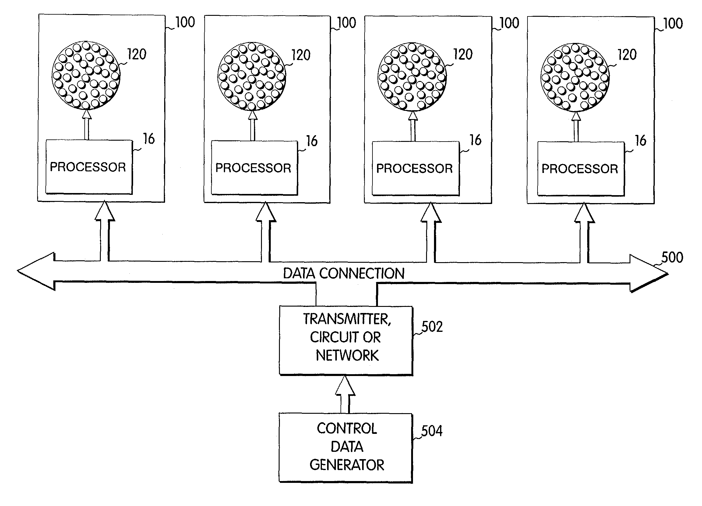
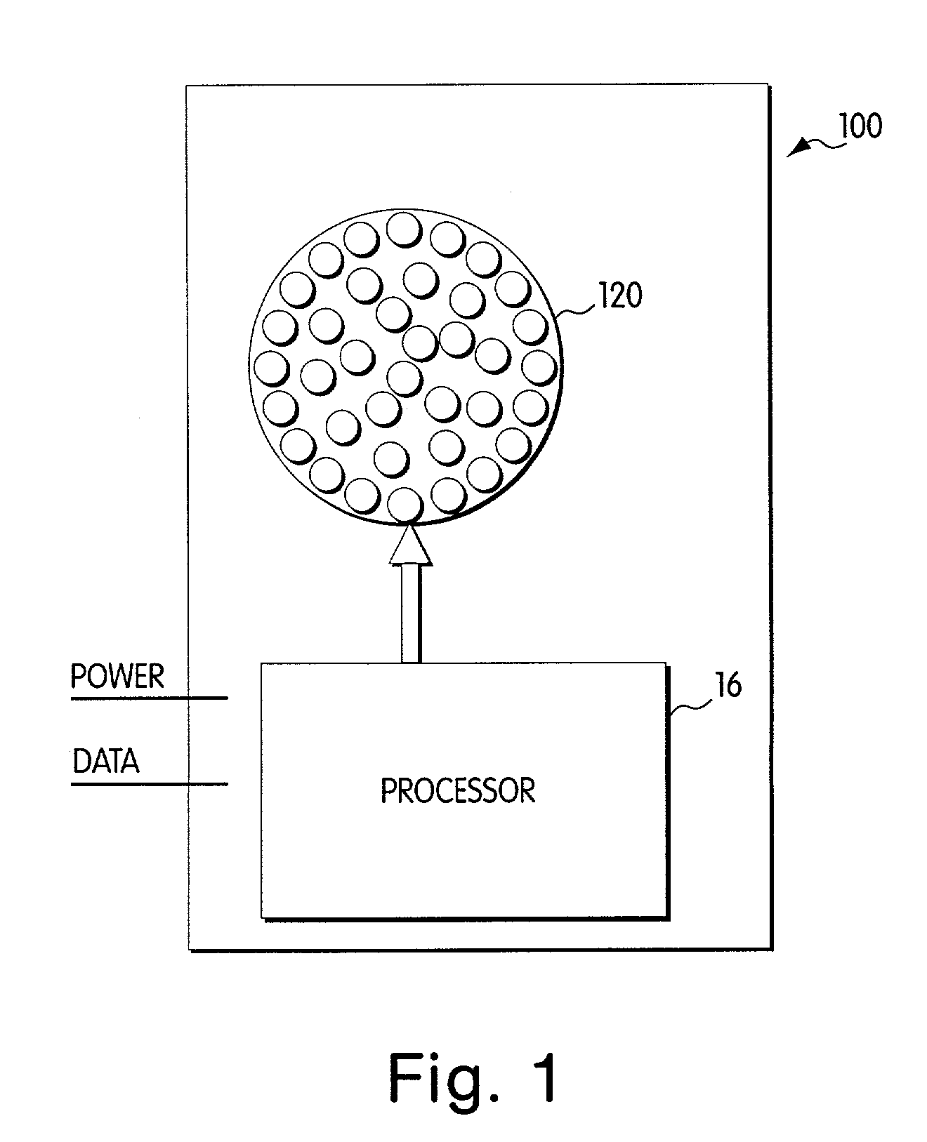
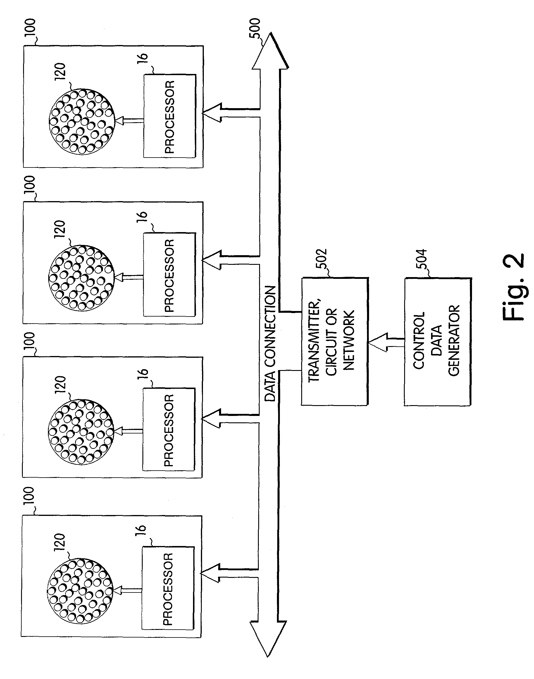
[0105]Referring to FIG. 1, a light module 100 is depicted in block diagram format. The light module 100 includes two components, a processor 16 and an LED system 120, which is depicted in FIG. 1 as an array of light emitting diodes. The term “processor” is used herein to refer to any method or system for processing in response to a signal or data and should be understood to encompass microprocessors, integrated circuits, computer software, computer hardware, electrical circuits, application specific integrated circuits, personal computers, chips, and other devices capable of providing processing functions. The LED system 120 is controlled by the processor 16 to produce controlled illumination. In pa...


PUM


Abstract

Linear lighting systems and methods. In one example, two or more lighting elements having an essentially linear or curvilinear shape are coupled together to form a lighting system. Each lighting element includes a group of LEDs arranged so as to illuminate the essentially linear or curvilinear shape of the lighting element. Each element may include LEDs to generate the same color light, and/or LEDs to generate light of different colors. Additionally, each element may include one or more controllers to control the LEDs so as to create a variety of temporal and/or color-oriented lighting effects. The controller(s) may employ one or more of a variety of control techniques to control the LEDs, such as those involving analog control signals or pulse-width modulated (PWM) control signals. The lighting elements of the system may each be configured as a “stand alone” unit working within the system, producing respective lighting effects that may or may not be coordinated with each other. Alternatively, two or more elements of the system may be configured as addressable lighting elements to facilitate coordination of the elements as a networked lighting system. Any of the foregoing linear lighting systems may be used in a variety of interior or exterior, as well as direct or indirect, lighting applications. In one example, such lighting systems are particularly well-suited as replacements or substitutes for neon lighting installations.

Description

CROSS-REFERENCE TO RELATED APPLICATIONS [0001]This application claims the benefit under 35 U.S.C. §120 as a continuation (CON) of U.S. patent application Ser. No. 09 / 213,540, filed Dec. 17, 1998, now U.S. Pat. No. 6,720,745 entitled “Data Delivery Track,” which application in turn claims the benefit under 35 U.S.C. §120 as a continuation-in-part (CIP) of U.S. patent application Ser. No. 08 / 920,156, filed Aug. 26, 1997, entitled “Multicolored LED Lighting Method and Apparatus,” now U.S. Pat. No. 6,016,038.[0002]This application also claims the benefit under 35 U.S.C. §120 of each of the following U.S. provisional applications, as at least one of the above-identified U.S. non-provisional applications similarly is entitled to the benefit of at least one of the following provisional applications:[0003]Ser. No. 60 / 071,281, filed Dec. 17, 1997, entitled “Digitally Controlled Light Emitting Diodes Systems and Methods;”[0004]Ser. No. 60 / 068,792, filed Dec. 24, 1997, entitled “Multi-Color In...

Claims


Application Information

Patent Timeline
IPC IPC(8): H05B37/00A61B6/00A61N5/06F21K99/00G09G3/14H05B37/02H05B44/00
CPCA61N5/0616G09G3/14G09G3/2014G09G3/32H05B33/0803H05B33/0818H05B33/0827H05B33/0857H05B33/0863H05B37/02H05B37/0254H05B37/029A61N5/0618F21Y2105/001A61N2005/0652F21S4/008F21V33/004F21V33/006F21W2111/027F21W2111/08F21Y2101/02G09G3/3283G09G2300/06G09G2320/0626G09G2320/0666Y02B20/346F21K9/13F21K9/30F21S2/00F21V23/0442F21S4/28F21K9/20F21Y2105/10F21K9/23F21Y2115/10H05B45/20H05B45/46H05B47/18H05B47/10H05B47/155H05B45/30H05B45/38H05B45/325Y02B20/30
Inventor LYS, IHOR A.MUELLER, GEORGE G.MORGAN, FREDERICK M.BLACKWELL, MICHAEL K.
Owner PHILIPS LIGHTING NORTH AMERICA CORPORATION
Why Eureka
Try Eureka