Vehicle lighting methods and apparatus

a technology for vehicles and lighting devices, applied in the direction of spectral modifiers, process and machine control, lighting support devices, etc., can solve the problems of reducing the number of messages sent to each set of dimmers, requiring special wiring or cabling, and inadequate positioning of mirrors and other mechanical devices. , to achieve the effect of limited life span

Inactive Publication Date: 2005-03-24
PHILIPS LIGHTING NORTH AMERICA CORPORATION
View PDF99 Cites 362 Cited by
  • Summary
  • Abstract
  • Description
  • Claims
  • Application Information

AI Technical Summary

Benefits of technology

[0024] Many conventional illumination applications are subject to other drawbacks. Conventional light sources, such as halogen and incandescent sources may produce undesirable heat. Such sources may have very limited life spans. Conventional light sources may require substantial lens and filtering systems in order to produce color. It may be very difficult to reproduce precise color conditions with conventional light sources. Conventional light sources may not respond quickly to computer control. One or more of these drawbacks may have particular significance in particular existing lighting applications. Moreover, the combination of these drawbacks may have prevented the development of a number of other illumination applications. Accordingly, a need exists for illumination methods and systems that overcome the drawbacks of conventional illumination systems and that take advantage of the possibilities offered by overcoming such drawbacks.

Problems solved by technology

The disadvantage is a reduction in the number of messages sent to each of the set of dimmers, in this example by a factor two.
Normal eight bit messages allow two hundred fifty-six positions, which is inadequate for the positioning of mirrors and other mechanical devices.
A significant problem with present lighting networks is that they require special wiring or cabling.
A second significant problem with present lighting networks is that particular lighting applications require particular lighting types.
Traditional methods of providing pulse width modulated signals include hardware using software programmed timers, which in some instances is not cost effective if not enough timer modules are available, and one interrupt per count processes, in which a microprocessor receives periodic interrupts at a known rate.
The difficulty with the third method is that for multiple PWM channels it is very difficult to arrange the timer based signal updates such that they do not overlap, and then to accurately change the update times for a new value of PWM signals.
Many conventional illumination applications are subject to other drawbacks.
Conventional light sources, such as halogen and incandescent sources may produce undesirable heat.
Such sources may have very limited life spans.
It may be very difficult to reproduce precise color conditions with conventional light sources.
Conventional light sources may not respond quickly to computer control.
Moreover, the combination of these drawbacks may have prevented the development of a number of other illumination applications.

Method used


Image

  • Vehicle lighting methods and apparatus
  • Vehicle lighting methods and apparatus
  • Vehicle lighting methods and apparatus

Examples


Embodiment Construction

[0095] The structure and operation of various methods and systems that are embodiments of the invention will now be described. It should be understood that many other ways of practicing the invention herein are available, and the embodiments described herein are exemplary and not limiting.

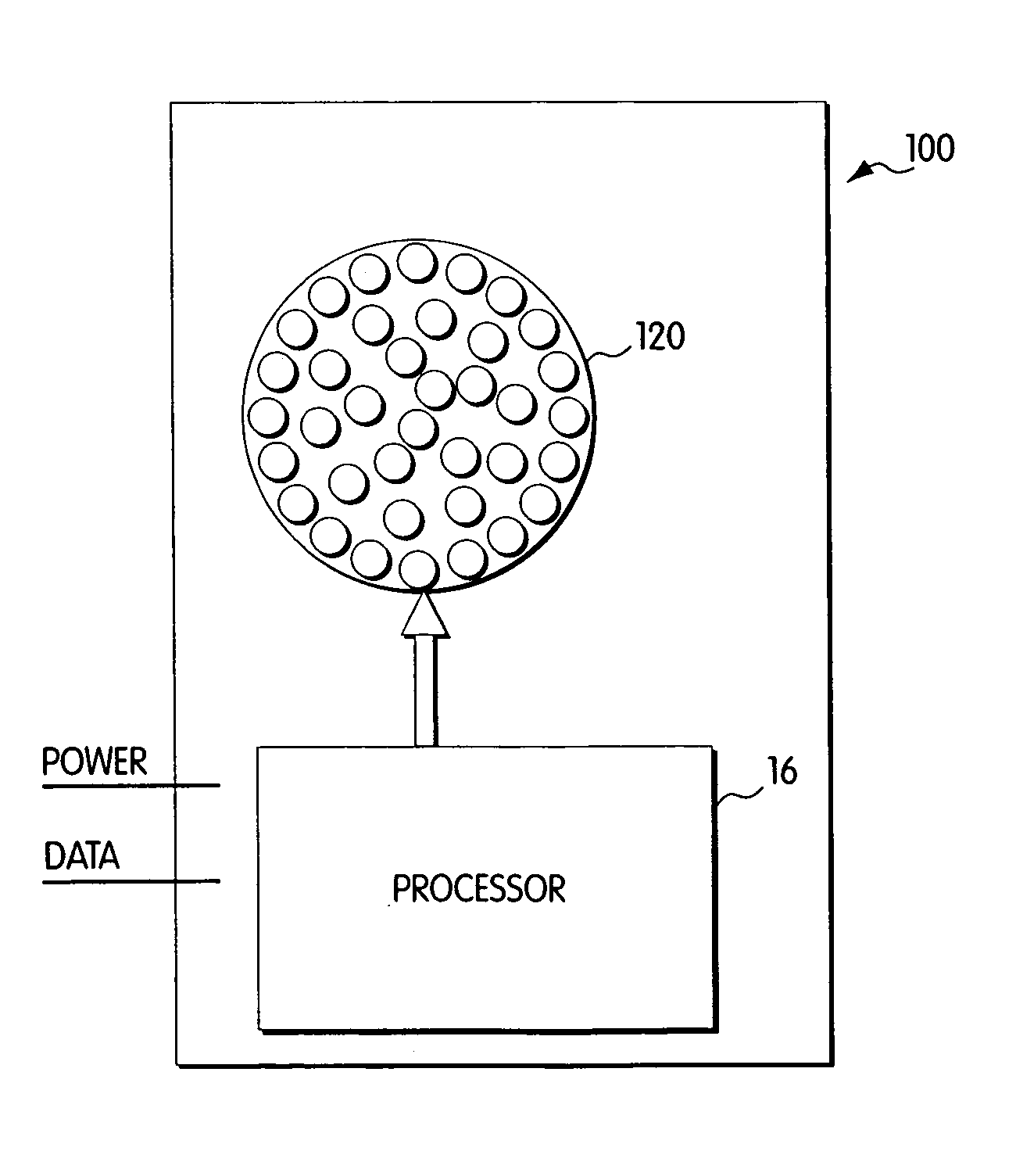
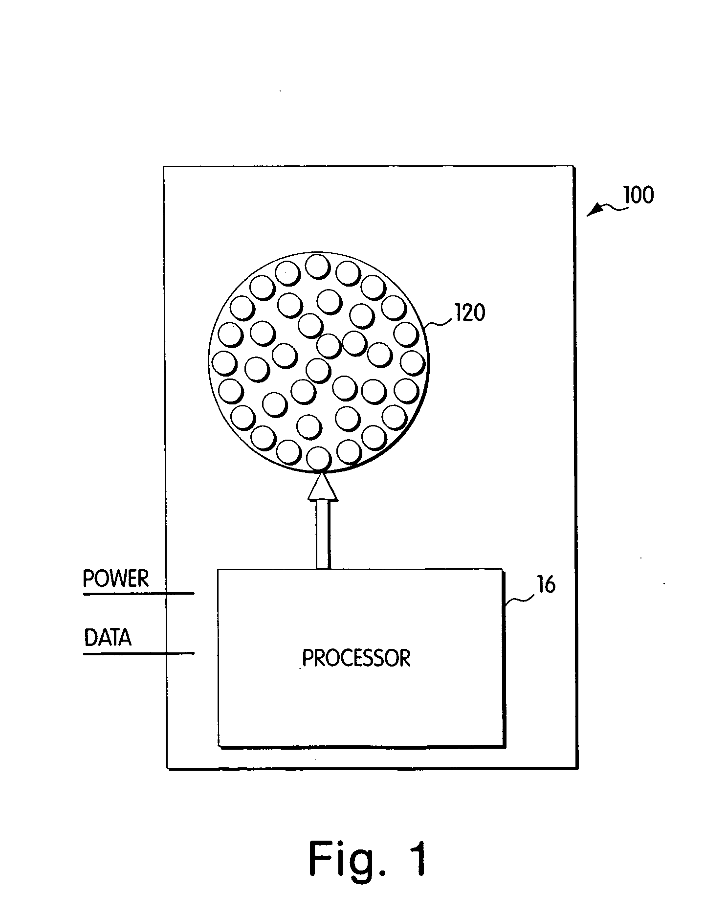
[0096] Referring to FIG. 1, a light module 100 is depicted in block diagram format. The light module 100 includes two components, a processor 16 and an LED system 120, which is depicted in FIG. 1 as an array of light emitting diodes. The term “processor” is used herein to refer to any method or system for processing in response to a signal or data and should be understood to encompass microprocessors, integrated circuits, computer software, computer hardware, electrical circuits, application specific integrated circuits, personal computers, chips, and other devices capable of providing processing functions. The LED system 120 is controlled by the processor 16 to produce controlled illumination. In...


PUM


Abstract

Vehicle lighting methods and apparatus, in which an LED-based light source is configured to generate at least visible radiation associated with a vehicle. The light source is controlled such that the generated visible radiation has a variable color over a range of colors including at least three different perceivable colors. Examples of vehicles in which such methods and apparatus may be used include, but are not limited to, an automobile, airplane, boat, non-motorized vehicle, etc. The LED-based light source may be disposed inside the vehicle (e.g., dashboard, instrument panel) or outside the vehicle (e.g., brake lights, undercarriage lighting), and may be controlled to generate white light as one of the perceivable colors. A user interface may be employed to facilitate an adjustment of the variable color of the generated visible radiation. Additionally, information relating to at least one condition associated with the vehicle may be employed to control the LED-based light source such that the variable color of the generated visible radiation is based at least in part on the condition associated with the vehicle.

Description

CROSS-REFERENCES TO RELATED APPLICATIONS [0001] This application claims the benefit under 35 U.S.C. §120 as a continuation (CON) of U.S. patent application Ser. No. 09 / 213,581, filed Dec. 17, 1998, entitled “Kinetic Illumination Systems and Methods.”[0002] Ser. No. 09 / 213,581 in turn claims the benefit under 35 U.S.C. §120 as a continuation-in-part (CIP) of U.S. patent application Ser. No. 08 / 920,156, filed Aug. 26, 1997, entitled “Multicolored LED Lighting Method and Apparatus,” now U.S. Pat. No. 6,106,038. [0003] Ser. No. 09 / 213,581 also claims the benefit of the following U.S. Provisional Applications: [0004] Ser. No. 60 / 071,281, filed Dec. 17, 1997, entitled “Digitally Controlled Light Emitting Diodes Systems and Methods”; [0005] Ser. No. 60 / 068,792, filed Dec. 24, 1997, entitled “Multi-Color Intelligent Lighting”; [0006] Ser. No. 60 / 078,861, filed Mar. 20, 1998, entitled “Digital Lighting Systems”; [0007] Ser. No. 60 / 079,285, filed Mar. 25, 1998, entitled “System and Method for...

Claims


Application Information

Patent Timeline
Patent Type & Authority Applications(United States)
IPC IPC(8): A61N5/06B60Q1/26B60Q1/44B60Q3/00B60Q3/02B60Q3/04F21S8/10G05F1/00H05B37/02H05B44/00
CPCA61N5/062B60Q1/2696B60Q1/44B60Q3/001B60Q3/0293Y10S362/80H05B33/0842H05B33/0857H05B33/0869H05B33/0872H05B37/0254B60Q3/048B60Q3/85B60Q3/80B60Q3/18H05B45/20H05B45/22H05B47/18H05B45/28H05B45/38H05B45/325H05B45/395
Inventor LYS, IHORMUELLER, GEORGE G.BLACKWELL, MICHAEL K.
Owner PHILIPS LIGHTING NORTH AMERICA CORPORATION
Why Eureka
Try Eureka