[0019]The present invention is directed to a wireless wastewater
system monitoring apparatus generally comprising a processor / transceiver unit, housed within a synthetic protective
enclosure formed outside of the wastewater system, and a fluid
level sensor configured to send an overflow signal to the processor / transceiver unit when an overflow condition in the wastewater system is detected. The processor / transceiver unit is configured with at least one
microprocessor wired between the sensor and a power supply and with a transceiver so as to detect the overflow signal from the sensor and, in response, transmit a wireless
alarm signal. The processor / transceiver unit is further configured such that only a portion of its circuitry is constantly powered so as to continuously monitor the sensor, while the remainder of its circuitry, including the transceiver, is only powered and a
wireless signal sent from the unit when an overflow condition is detected or a routine status-check is being conducted. In one exemplary embodiment, the processor / transceiver unit includes two microprocessors, a first that is “always on” and a second that is “powered up” in response to an awake signal from the first and that then powers up and controls the transceiver. In a second exemplary embodiment, a single
microcontroller having a standby
clock mode and a normal
clock mode achieves the minimal “always on” and responsive “powered up” function of the processor / transceiver unit. The
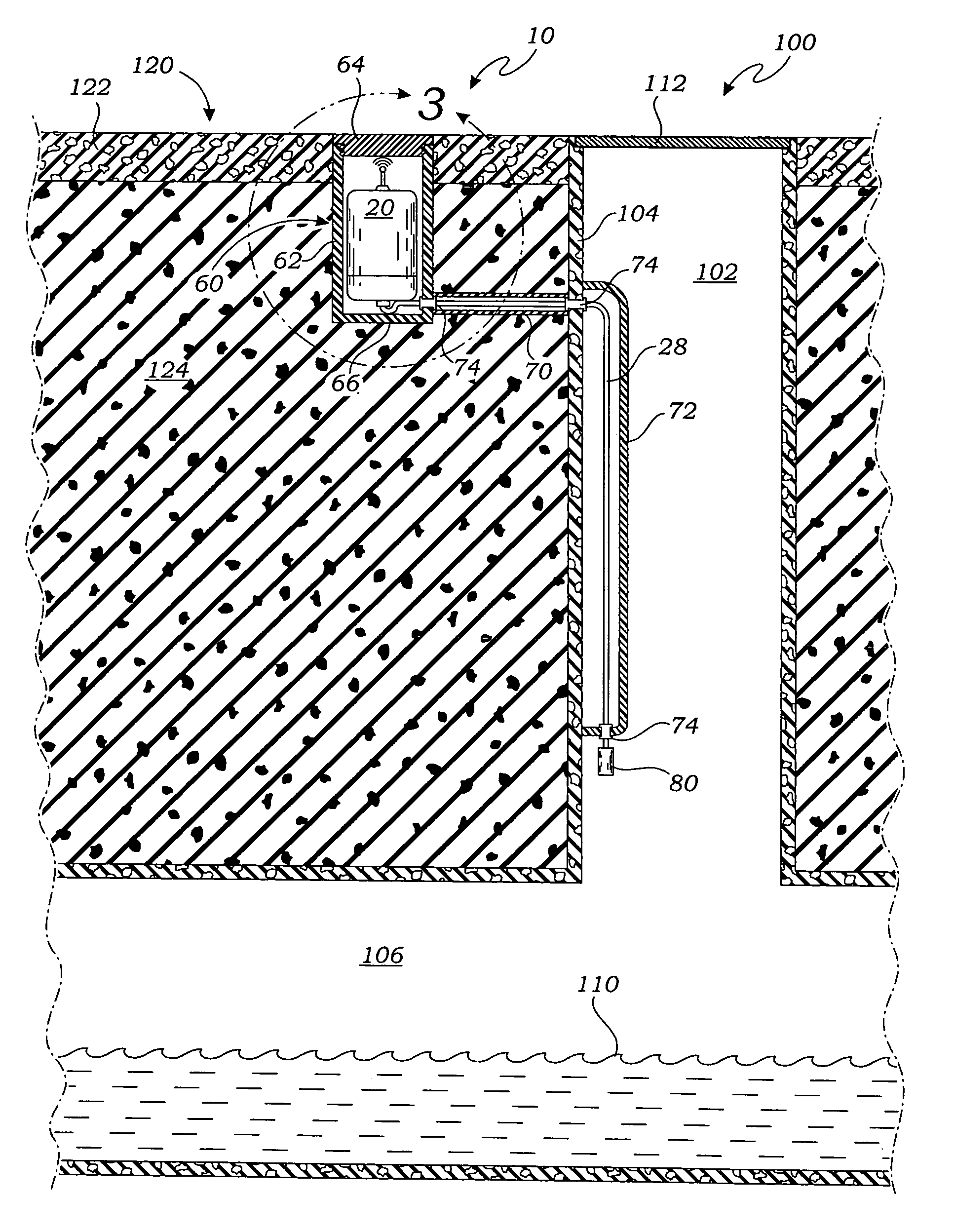
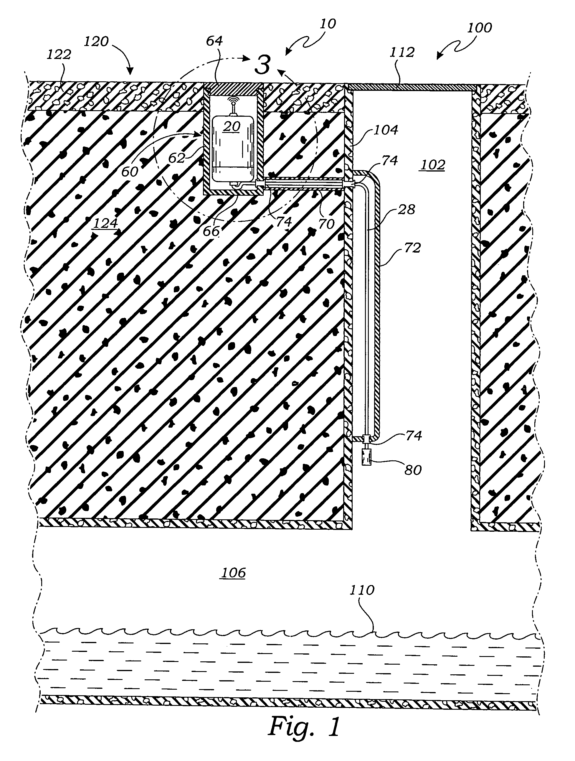
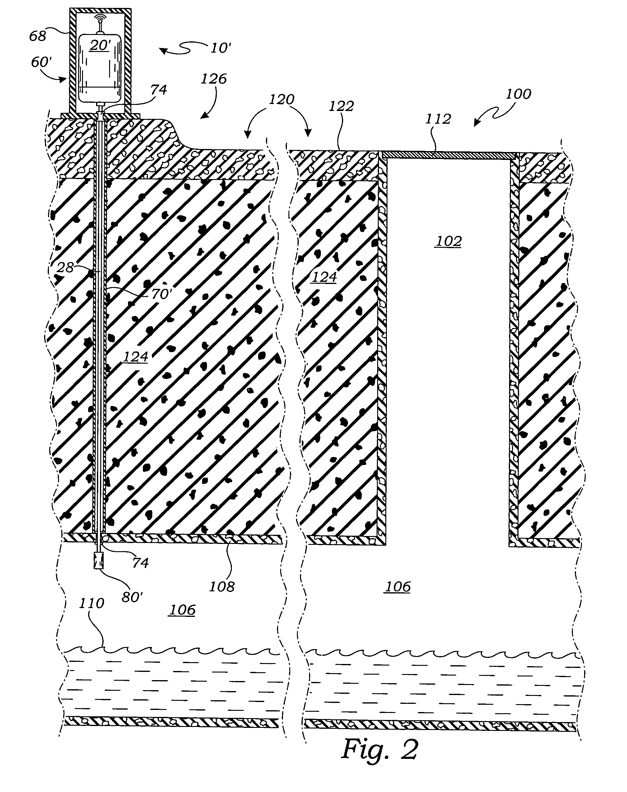
enclosure within which the processor / transceiver unit is housed may be a lined hole adjacent to a manhole or an above-ground container. By locating the processor / transceiver unit outside of the wastewater system, and particularly a manhole, the unit is protected from the harmful, corrosive effects of the wastewater system and is able to transmit wireless signals more reliably and with relatively less power by avoiding the attenuating effects of the manhole cover.
[0020]In use, the processor / transceiver unit is positioned within the protective enclosure and the fluid
level sensor is located in the wastewater system at a selected height above the
normal fluid level. The processor / transceiver unit defaults to a standby mode in which the sensor is continuously powered by the power supply and monitored under the control of the microprocessor, while the other components of the processor / transceiver unit, including the transceiver, are not powered. When the fluid level rises and an overflow condition is detected, the sensor sends an overflow signal to the microprocessor of the processor / transceiver unit. In response to the overflow signal, the microprocessor then “awakens” the rest of the processor / transceiver unit and transmits a wireless
alarm signal via the transceiver. The alarm signal, which contains information related to the location of the overflow condition, is routed through a wireless carrier to a
network operations center for notification to the appropriate district operator for corrective action. Once the overflow condition has been corrected, a reset signal is transmitted to the district operator again through the wireless carrier and
network operations center. The microprocessor may also be programmed to awaken at routine intervals and perform a status-check of the processor / transceiver unit, including
verification of the remaining battery life, and send a status-result signal to the
network operations center. The alarm, reset and status-result signals may be compressed before being transmitted by the processor / transceiver unit and decompressed upon
receipt at the network operations center, thereby further reducing wireless airtime. By only powering up the entire processor / transceiver unit when an overflow condition has been detected or a routine status-check is being conducted,
power consumption and wireless airtime are further minimized.
[0022]Another objective is to provide such an invention capable of reducing the
exposure of the wastewater system monitoring device processor / transceiver unit to the corrosive and contaminating effects of the wastewater system.
[0023]Yet another objective is to provide such an invention capable of reducing the attenuation of the wireless signals transmitted to and from the wastewater system monitoring device processor / transceiver unit.
[0025]Another objective is to provide such an invention capable of reducing the
power consumption by the wastewater system monitoring device.
[0027]Another objective is to provide such an invention capable of reducing the total wireless airtime used by the wastewater system monitoring device.

