Cutting apparatus with dust discharging

a cutting machine and dust discharge technology, applied in metal-working machines, portable grinding machines, manufacturing tools, etc., can solve the problems of incompatibility with other circular blades (disk cutters) of different sizes, and achieve the effects of superior sealing characteristics, heat resistance, and high flexibility

Inactive Publication Date: 2007-05-29
GOEI
View PDF13 Cites 48 Cited by
  • Summary
  • Abstract
  • Description
  • Claims
  • Application Information

AI Technical Summary

Benefits of technology

[0008]This structure can prevent fine chips (powder dust) from sticking to the flat belt or the pulley. The sealing member is made of felt with (1) a higher flexibility than the case, such as rubber or plastic, so that it has a superior sealing characteristic because a contact part with a peripheral surface of the output shaft or the rotation member tends to be fit to a configuration of this peripheral surface. Further, this structure provides (2) heat resistance against rotation friction, and (3) resistance to wear against the rotation friction.
[0009]According to the present invention, sticking of dust to the flat belt or the pulley within the dust cover can be prevented. This can also provide a high durability to the seal member.
[0013]According to the sander with this structure, the adjusting mechanism has a simple structure, so that a low cost sander is provided because of ease in assembling.
[0015]According to the sander having this structure, a simple sleeve member without the guard can sufficiently operate as a pulley having a guard. For example, if the pulley is formed as a metal member subjected to a cutting process, a guard-making process is unnecessary, and thus the manufacturing process can be simplified because the adjuster ring has a diameter larger than that of the pulley.
[0016]A further aspect of the present invention provides the cutting apparatus further comprising a spacer provided between the body and the dust cover to prevent interference between the part of the dust discharging unit and the body. A part of the dust discharging unit may be arranged adjacent to a side of the body. Thus, the position of the body in height can be made different from the position of the part of the dust discharging unit, which can prevent interference therebetween. In general cutting processes, it is not common to change the body with respect to the same dust cover. Thus, the structure with the spacer does not largely affect the efficiency of the cutting process.

Problems solved by technology

However, in the structure of the sander disclosed in Japanese Laid-open patent application publication No. 2000-210866, because the pulley and the flat belt is exposed to the inside of the dust cover, there is a problem that the fine chips (powder dust) within the dust cover may stick to these members, which can cause slippage therebetween.
On the other hand, due to a lack of compatibility, the dust cover is typically specially designed for each type of the sander.
In the dust cover disclosed in Japanese Laid-open patent application publication No. 2000-210866, there is a problem that the heights of the dust covers from the body to the edge portion are the same, so that there is no compatibility with other circular blades (disk cutters) having different sizes.

Method used


Image

  • Cutting apparatus with dust discharging
  • Cutting apparatus with dust discharging
  • Cutting apparatus with dust discharging

Examples


first embodiment

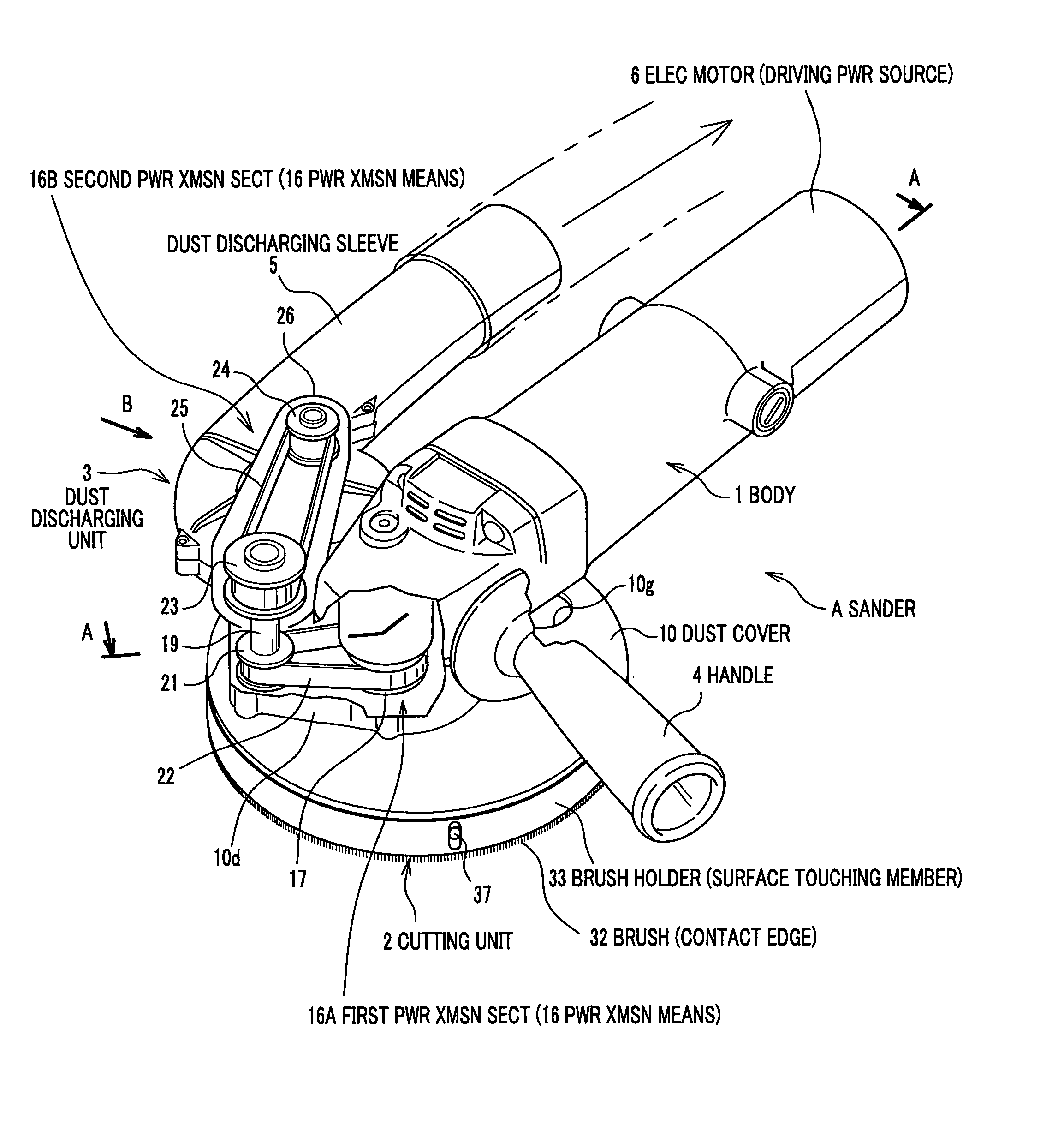
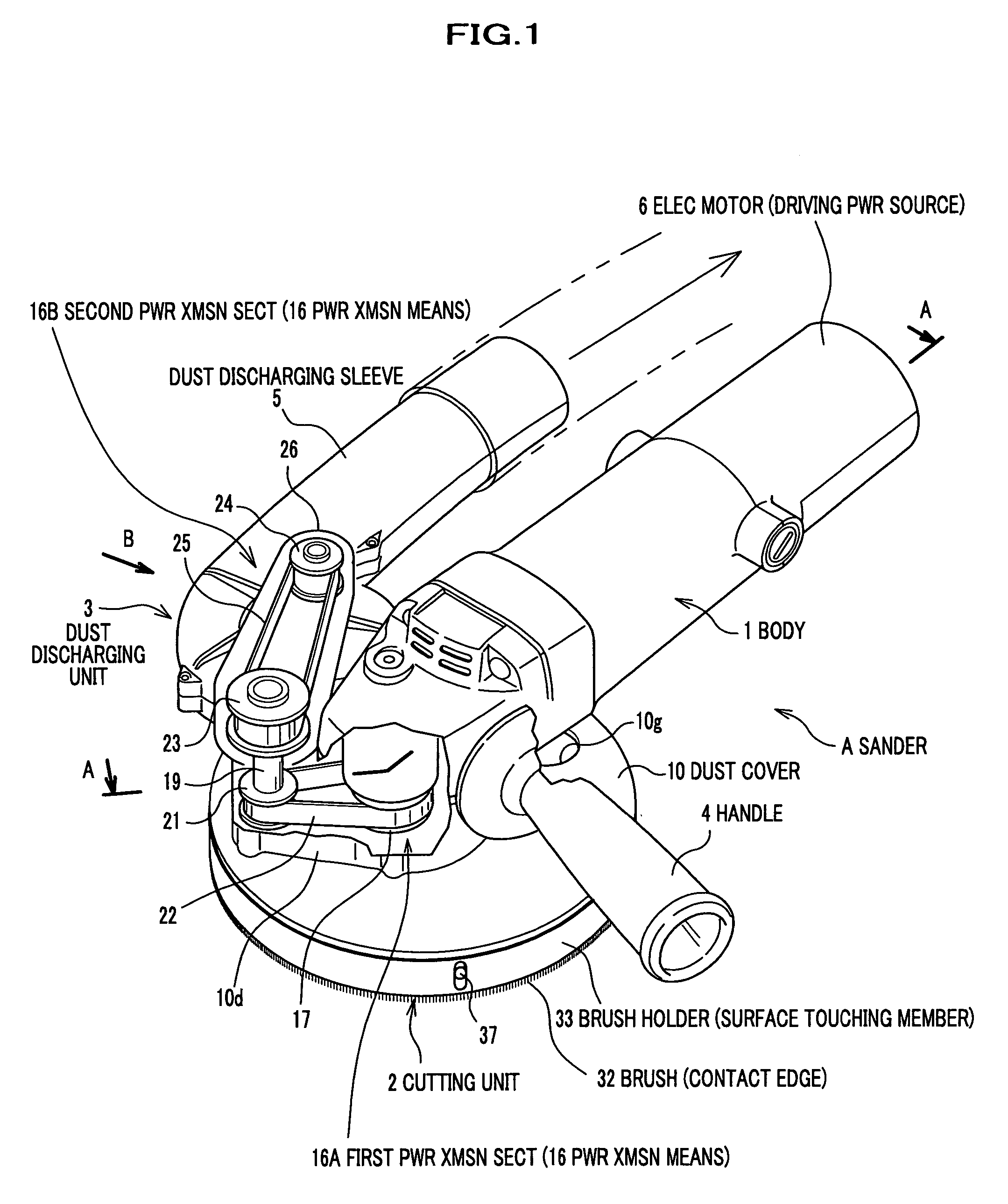
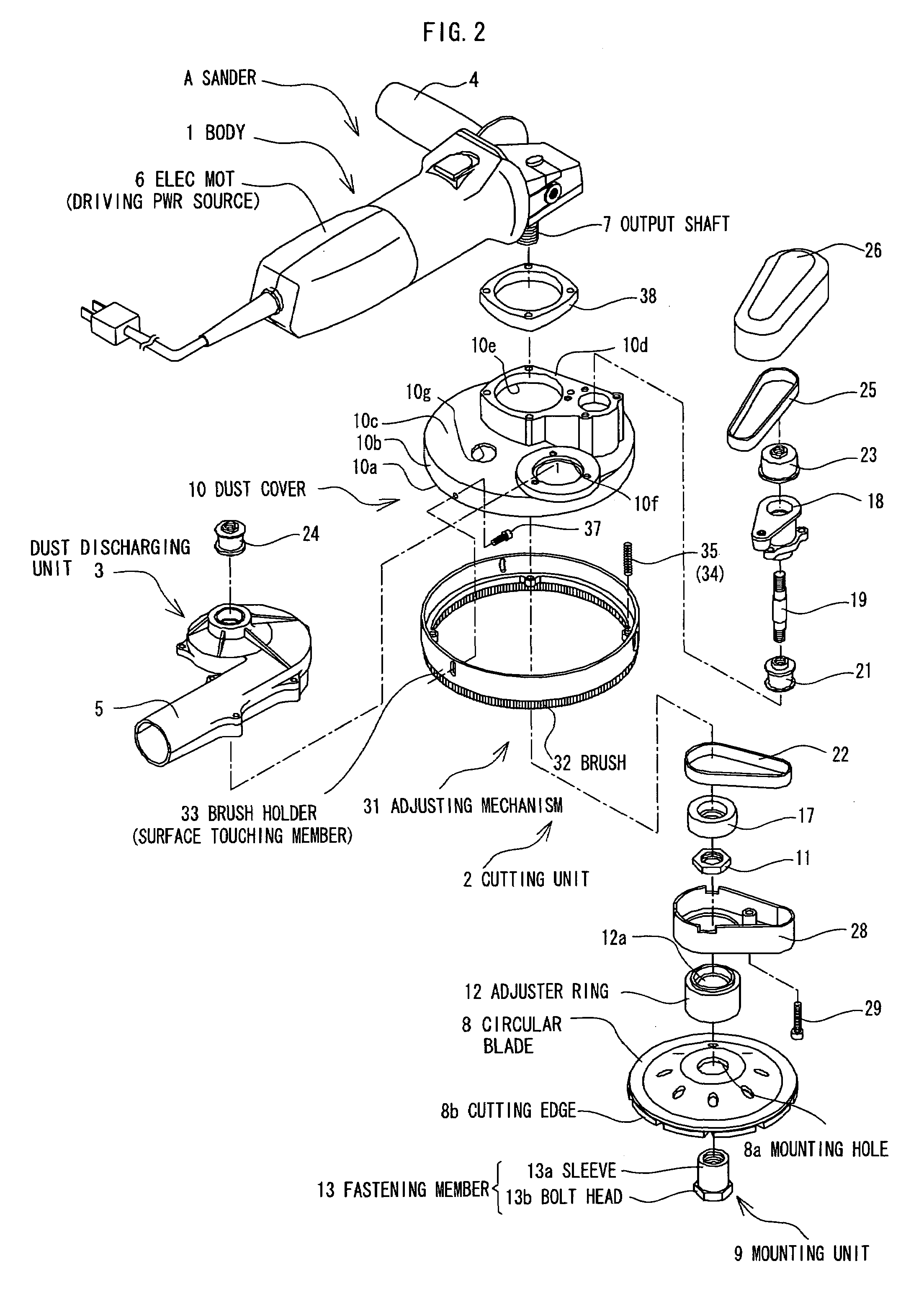
[0038]In FIG. 1, the hand-held sander A comprises a body 1, a cutting unit 2 mounted on an under part of one side of the body 1, and a dust discharging unit 3 attached or connected to the cutting unit 2 and arranged adjacent to a side of the body 1.

[0039]The body 1 is provided with a handle 4 to be gripped by an operator at the opposite side to the side of the body 1. The dust discharging unit 3 comprises a discharging sleeve 5 connected to a dust collecting bag (not shown). The body 1 comprises an electric motor 6 as a driving power source of the cutting unit 2 and an output shaft 7 connected or coupled to the electric motor 6.

Cutting Unit 2

[0040]Cutting edges 8b comprise carbide tools, grindstones, a diamond wheel, or the like. At a center of a top part of a circular blade (disk cutter) 8, a mounting hole 8a is formed for mounting the circular blade 8 on the output shaft 7.

[0041]The configuration of the circular blade 8 is not limited to that shown in the drawing. For example, the...

second embodiment

[0102]FIGS. 8 and 9 illustrate a second embodiment of a cutter. FIG. 8 is a perspective view of the cutter, and FIG. 9 is a partial perspective view illustrating a de-assembled condition, wherein a second cover, mentioned later, is removed.

[0103]In this embodiment, the same members as those described in the first embodiment are designated with the same references. Descriptions about portions other than the main portion will be omitted in the following description.

[0104]In the hand-held cutter C, a body 1 including the electronic motor 6 is so inclined that the axial direction of an output shaft 7 extends in the horizontal direction, and the tip of the output shaft 7 enters the inside of a dust cover 41 of the cutting unit 2.

[0105]The dust cover 41 is provided with an opening edge 41a facing a workpiece. An outline configuration viewed from the axial direction of the output shaft 7 is substantially a semi-circle in which the opening edge 41a corresponds to the side of the semi-circle...


PUM


Abstract

In a cutting apparatus having a circular blade with a dust discharging unit for, during cutting, discharging chips (dust) within a dust cover covering the circular blade, a pulley is fixed to an output shaft of a power source, and a flat belt for transmitting power to the dust discharging unit is engaged with the pulley. The pulley and the flat belt are covered with an inner cover within the dust cover. The inner cover has a through hole for allowing the output shaft to protrude the inner cover therethrough with a seal made of felt to prevent dust from entering the inside of the inner cover. A surface touching member is provided around an opening edge of the dust cover movable along an axial direction of the output shaft by spring-loading, which automatically reduces the gap between the dust cover and the object to prevent dust from being scattered.

Description

FIELD OF THE INVENTION[0001]The present invention relates to a cutting apparatus used for at least one of cutting and grinding of an object to be cut, such as concrete blocks and stone works, and particularly to hand-held cutters for cutting an object and to a hand-held sander for grinding an object.BACKGROUND OF THE INVENTION[0002]Cutting apparatuses including a circular blade (disk cutter) for cutting objects and sanders for grinding a surface of an object such as concrete blocks are known. Japanese Laid-open patent application publication No. 2000-210866 discloses such a sander (see pages 1 to 2, FIGS. 1–2). This conventional sander is used in such a manner that one side of rotating cutting edges of a circular blade is pressed on the surface of the object. The sander mainly includes a body having a driving power source for a circular blade (disc cutter), a cutting unit, mounted on the body, having the circular blade, a dust cover (chip guard) for covering the circular blade, and ...

Claims


Application Information

Patent Timeline
Patent Type & Authority Patents(United States)
IPC IPC(8): B24B23/00B24B55/10
CPCB24B7/186B24B23/028B24B55/102
Inventor KODANI, MITSUNORITACHIBANA, KAZUMASA
Owner GOEI
Why Eureka
Try Eureka