Hybrid-vehicle drive system and operation method with a transmission

Inactive Publication Date: 2007-05-29
TOYOTA JIDOSHA KK
View PDF78 Cites 144 Cited by
  • Summary
  • Abstract
  • Description
  • Claims
  • Application Information

AI Technical Summary

Benefits of technology

[0019]As described above, in the hybrid-vehicle drive system in which the output shaft of the internal combustion engine is connected to the first motor/generator and the wheel drive shaft via the power distribution mechanism, the transmission is located on the wheel drive shaft or in a connecting portion of the second electric motor/generator with the wheel drive shaft. In an arrangement in which the transmission is located on a portion of the wheel drive shaft that is closer to the internal combustion engine than the connecting portion of the second motor/generator, if the drive system is required to generate high vehicle-axis torque at a low vehicle speed, the speed of rotation of the internal combustion engine is increased in relation to the vehicle speed by controlling the power distribution mechanism, and the speed reduction ratio of the transmission is increased so that the engine provides a larger portion of the required high vehicle-axis torque. Thus, the required high torque can be provided at a low vehicle speed while reducing the magnitude of torque that needs to be generated by the second motor/generator. In another arrangement in which the transmission is located on a portion of the wheel drive shaft that is remote from the internal combustion engine with respect to the connecting p

Problems solved by technology

It appears from FIG. 3 that the depth of the region C is considerably large as compared with the region B. The imbalance between the region C and the region B may lead to an imbalance in the size amo

Method used


Image

  • Hybrid-vehicle drive system and operation method with a transmission
  • Hybrid-vehicle drive system and operation method with a transmission
  • Hybrid-vehicle drive system and operation method with a transmission

Examples


Example

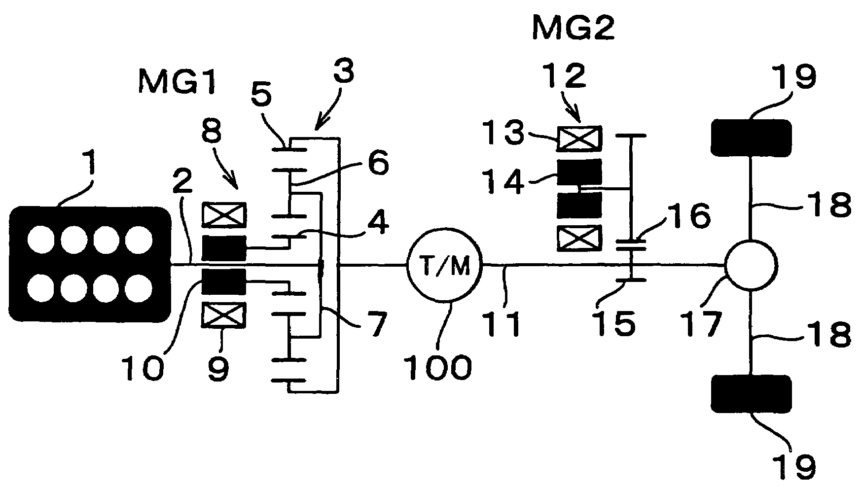
[0037]In a first embodiment shown in FIG. 4, a transmission 100 is disposed in an intermediate portion of the wheel-drive shaft at one side of a connecting portion of the second electric motor / generator MG2 closer to the internal combustion engine. In other words, the transmission 100 is disposed in a portion of the propeller shaft 11 as one part of the wheel-drive shaft, such that the transmission 100 is located on one side of the gear 15 that provides the connecting portion of the MG2, which side is closer to the internal combustion engine 1. The transmission 100 may have two or three gear ratios or gear positions, and may also have a reverse gear position. Such a transmission can be provided in various manners by using known techniques. An example of a transmission including three forward-drive gear positions and one reverse-drive gear position is schematically shown in FIG. 7.

[0038]In FIG. 7, reference numerals 20, 22, 24 and 26 denote a sun gear, a ring gear, planetary pinions,...

Example

[0040]In a second embodiment as shown in FIG. 5, a transmission 101 is disposed in an intermediate portion of the wheel-drive shaft on one side of the connecting portion of the second electric motor / generator MG2 remote from the internal combustion engine. In other words, the transmission 101 is disposed in a portion of the propeller shaft 11 as one part of the wheel-drive shaft such that the transmission 101 is located on one side of the gear 15 that provides the connecting portion of the MG2, which side is remote from the internal combustion engine with respect to the connecting portion. The transmission 101 may have two or three forward-drive gear positions and may also have a reverse-drive gear position. The transmission 101 may be constructed as shown in FIG. 7.

[0041]When a transmission having three gear positions is used as the transmission 101 in the driven system of the embodiment as shown in FIG. 5, the relationship (or ratio) between the torque to be produced by the intern...

Example

[0042]In a third embodiment shown in FIG. 6, a transmission 102 is disposed in a connecting line or path between the wheel-drive shaft and the second electric motor / generator MG2. In other words, the transmission 102 is disposed in a connecting portion of the MG2 that connects the MG2 with the propeller shaft 11 as a portion of the wheel drive shaft. The transmission 102 may have two or three gear ratios or positions. With the above arrangement, the transmission 102 need not have a reverse-drive gear position since the MG2 can be driven in the reverse direction by switching an electric circuit for the MG2. Nevertheless, the transmission 102 may have a reverse gear position, or may be constructed as shown in FIG. 7.

[0043]When a transmission having three gear positions is used as the transmission 102 in the embodiment shown in FIG. 6, the relationship (or ratio) between the torque to be produced by the internal combustion engine 1 and the torque to be produced by the MG2, when viewed ...


PUM


Abstract

A hybrid-vehicle drive method and system includes an internal combustion engine that includes an output shaft, a first electric motor/generator connected to the output shaft of the internal combustion engine via a power distribution mechanism, a wheel drive shaft connected to the output shaft of the internal combustion engine via the power distribution mechanism, a second electric motor/generator connected to the wheel drive shaft, and a transmission located on at least one of the wheel drive shaft and a connecting portion of the second electric motor/generator with the wheel drive shaft.

Description

INCORPORATION BY REFERENCE[0001]The disclosure of Japanese Patent Applications Nos. 2001-323578, 2001-323931 and 2001-324064 filed on Oct. 22, 2001, each including the specification, drawings and abstract, is incorporated herein by reference in its entirety.BACKGROUND OF THE INVENTION[0002]1. Field of Invention[0003]The invention relates to a drive system for hybrid vehicles, which drives wheels by using a combination of an internal combustion engine and electric motors.[0004]2. Description of Related Art[0005]As conservation of air environment and saving of fuel resources become increasingly important, hybrid vehicles whose wheels are driven by a combination of an internal combustion engine and an electric motor (or motors) have been attracting much attention in the field of automobiles. In the hybrid vehicles, wheels are driven in various manners by an internal combustion engine and an electric motor (or motors) arranged in various forms so as to achieve a wide variety of combinat...

Claims


Application Information

Patent Timeline
IPC IPC(8): B60K1/02F16H3/72F16H35/02F16H37/06F16H37/12B60K6/365B60L50/16B60K6/40B60K6/445B60K6/48B60K6/54B60K6/547B60W10/06B60W10/08B60W10/10B60W20/00B60W30/18F16H59/08
CPCB60K6/40B60K6/445B60K6/48B60K6/547B60W10/06B60W10/08B60W10/115B60W20/00F16H3/727B60K6/365B60K1/02Y10T477/23B60L2240/423B60L2240/486B60W30/18036B60W2710/0666B60W2710/083B60W2710/105F16H2037/0866F16H2059/085Y02T10/6221Y02T10/6286Y02T10/642Y02T10/6239B60L2200/26Y02T10/62Y02T10/64B60W20/30
Inventor KOJIMA, MASAKIYOTAKAOKA, TOSHIFUMITAGA, YUTAKA
Owner TOYOTA JIDOSHA KK
Why Eureka
Try Eureka