Method and system for microfluidic interfacing to arrays

a microfluidic interfacing and array technology, applied in the direction of fluid speed measurement, flow mixer, flat carrier support, etc., can solve the problems of limited microarray processing time and care, no method has been completely satisfactory, so as to achieve better results, more controllable delivery of reactants, and more successful processing of microarrays

Inactive Publication Date: 2007-05-29
ROCHE NIMBLEGEN
View PDF160 Cites 152 Cited by
  • Summary
  • Abstract
  • Description
  • Claims
  • Application Information

AI Technical Summary

Benefits of technology

[0019]The interface device seals against the surface of the microarray substrate. A sealing layer or gasket positioned between the interface device and substrate provides a uniform, non-leaking seal between the interface device and substrate. A clamp mechanism may be used to secure the interface device and substrate together. Indentations or grooves in surface of the interface device are aligned with spots in the microarray, so that when the interface device is sealed to the microarray substrate, the indentations or grooves form one or more reaction chambers, chambers or channels containing spots in the microarray. Alternatively, interface channels, chambers, or wells may simply be defined by openings in a sealing or gasket layer. Interface channels, chambers, or wells may access individual spots, groupings of spots, e.g. rows or blocks of spots within the array, or all spots in the array. Size and configuration of interface channels or wells are selected to provide uniform filling with minimal bubble formation. Interface channel volumes are kept low to reduce the amounts of sample and reagents that must be used.
[0033]It is an object of the invention to provide a system for performing manual processing of individual microarray slides in a reliable and reproducible fashion. This is accomplished through the use of an interface device that receives manually delivered reagents and reactants and provides them to the surface of a microarray slide in a controlled manner.

Problems solved by technology

However, a current limitation of microarrays is the time and care required to process slides to obtain reliably high quality results.
The need for high quality processing is particularly pronounced because individual microarrays slides are expensive and only limited quantities of the samples used in the reactions may be available, making it particularly important to obtain good results consistently.
However, to date, no method has been completely satisfactory.
Each processing step must be carried out by hand, necessitating a large amount of human effort.
An additional drawback of manual processing techniques is that an essentially open system is used, presenting a high potential for evaporation, spilling or leakage of samples or reagents.
If microarray slides are allowed to dry out, data quality will be compromised.
Leakage and spilling can be a significant problem, in that certain samples or reagents may be hazardous, and also because leakage or spilling of genetic material, even in minute amounts, can contaminate other samples being processed in the lab and lead to erroneous results.
These range from simple slide processing chambers designed to simplify the application of solutions to microarray slides and reduce evaporation and leakage of solutions, to large and expensive machines capable of processing large numbers of slides simultaneously.
Devices for automated processing of microarray slides offer many advantages, but are prohibitively expensive for labs that do not need to process large numbers of slides.
In addition, even with improved reproducibility delivered by automation, the results obtained with commercially available instruments of this type frequently do not meet the high quality and consistency standards that are desirable, particularly because of the cost of microarray slides and the often limited availability of samples.

Method used


Image

  • Method and system for microfluidic interfacing to arrays
  • Method and system for microfluidic interfacing to arrays
  • Method and system for microfluidic interfacing to arrays

Examples


Embodiment Construction

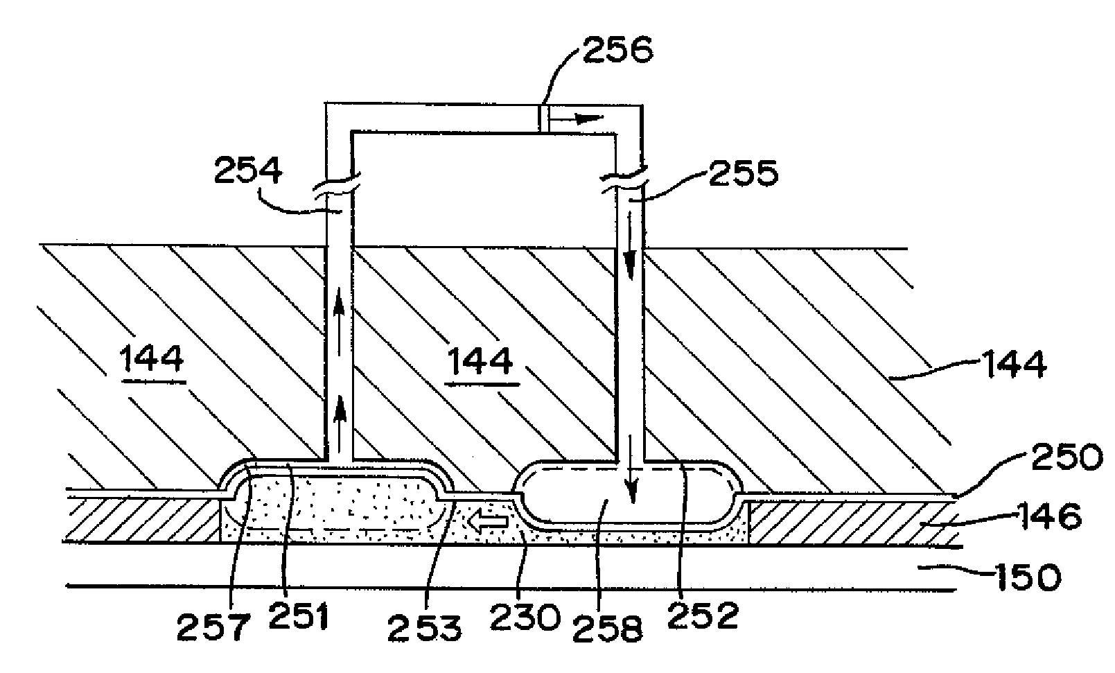
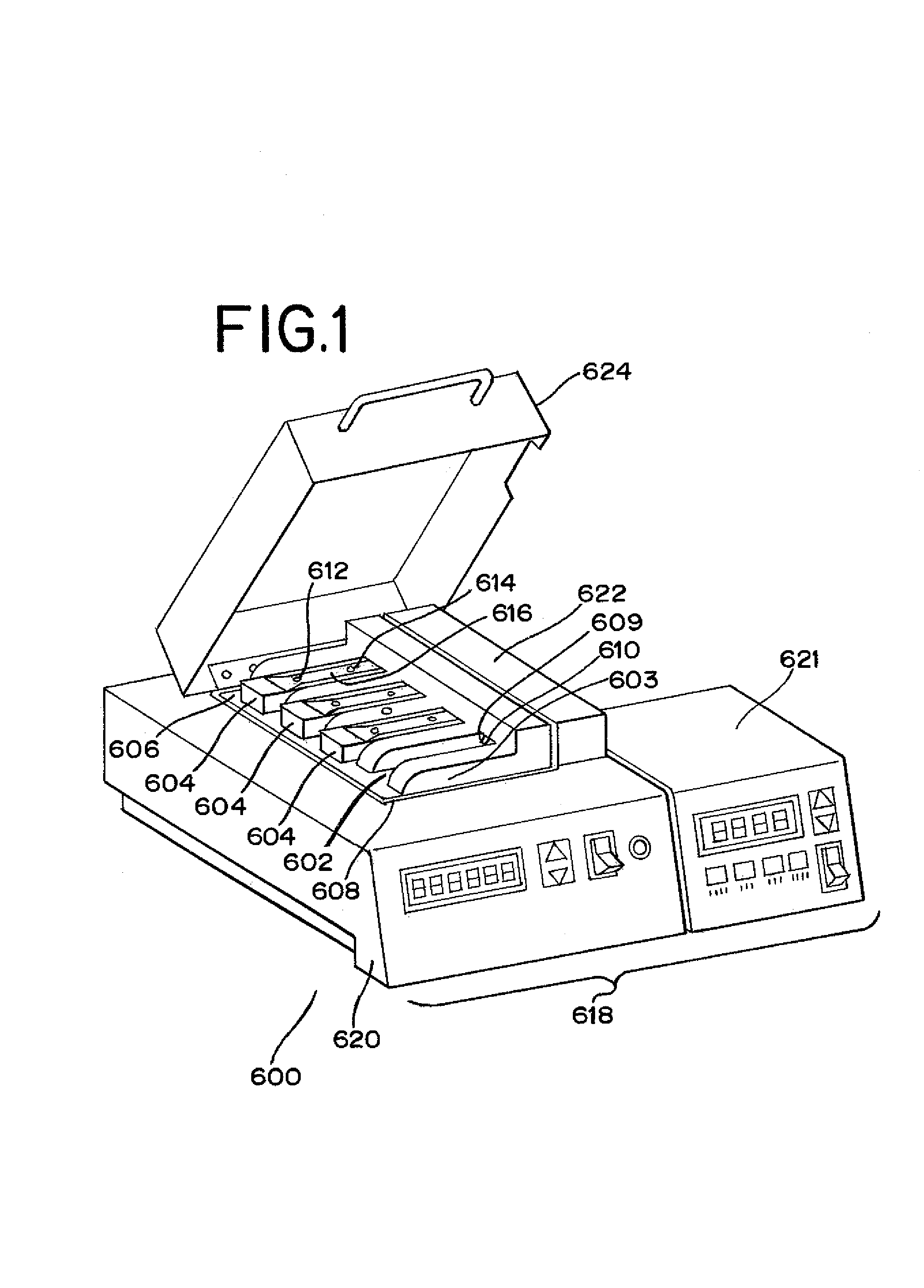
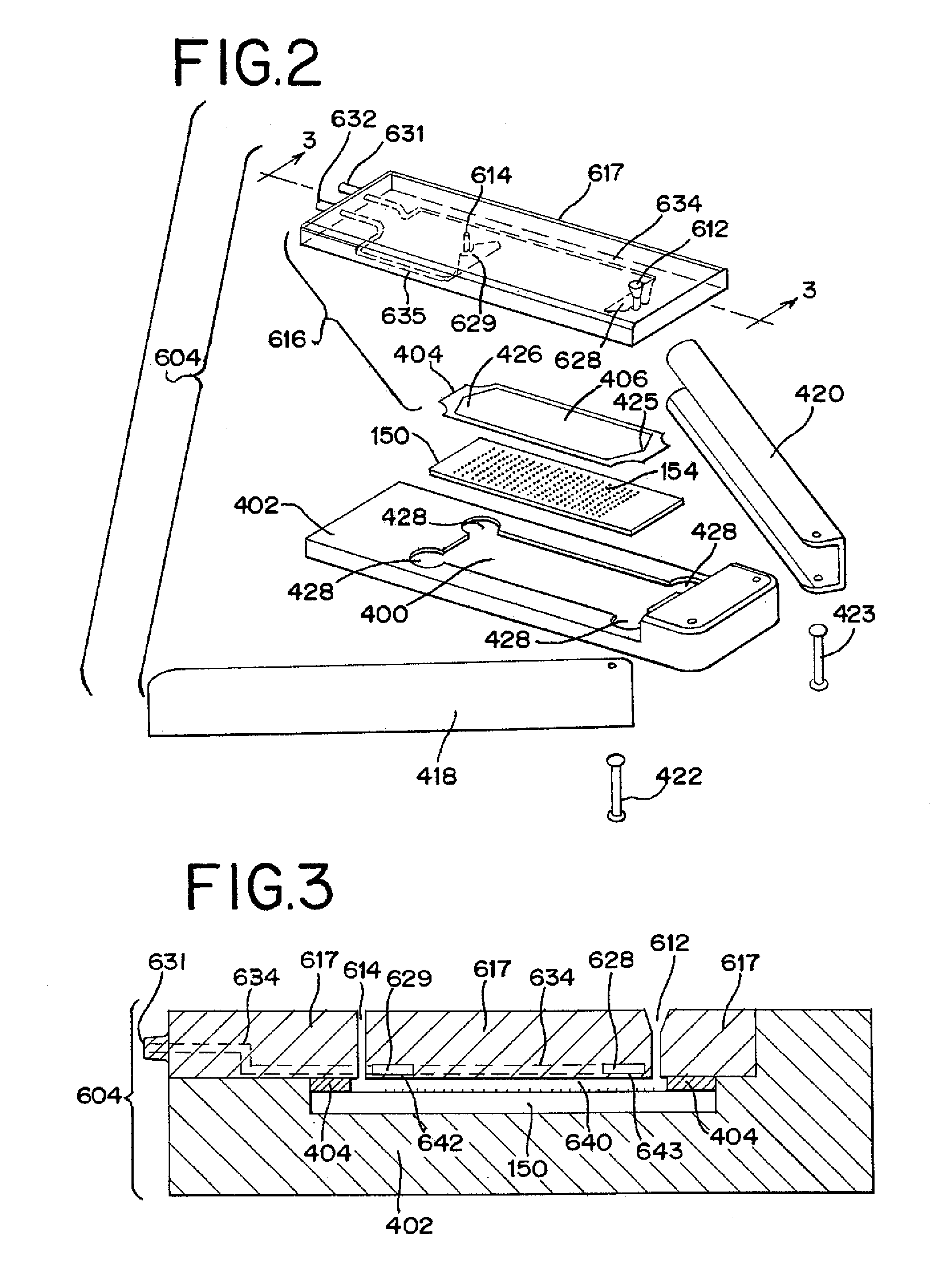
[0081]FIG. 1 depicts an example of a presently preferred embodiment of the invention. The invention includes an instrument 600, which includes multiple bays 602, each of which is adapted to receive a reaction device 604, which is made up of a microarray slide in combination with a microarray interface device. Bays 602 are located in base 603 on heat block 606, which fits into well 608 in instrument 600. Base 603 is formed as a part of heat block 606, or is formed separately and mounted on heat block 606. In either case, base 603 and bays 602 are in thermal communication with heat block 606. Reaction devices 604 are heated by heat block 606 during microarray processing. Each reaction device 604 mates with air connectors 609 and 610, visible in the empty bay 602. Air line connectors 609 and 610 are connected to a pressure source in instrument 600, which is used to drive mixing of fluid in reaction device 604. In the embodiment of the invention depicted in FIG. 1, sample, reagent, and ...


PUM

PropertyMeasurementUnit
heightaaaaaaaaaa
heightaaaaaaaaaa
heightaaaaaaaaaa

Abstract

A method and system for providing a fluidic interface to slides bearing microarrays of biomolecules or other samples immobilized thereon to perform a variety of chemical reactions or processing steps on the slide. An interface device seals against the slide to form a chamber or chambers containing all or a portion of the microarray, providing selective access to portions of the slide. The interface device includes inlet and outlet ports permitting liquid sample and reagents to be introduced to and removed from the chamber accessing the slide surface. Pre- and post-array microfluidic circuitry may be included in the interface device or in attachable modules. The system may include one or more compartments for collecting and storing waste fluids.

Description

RELATED APPLICATIONS[0001]This application claims the benefit of U.S. Provisional Application Ser. No. 60 / 274,389 filed Mar. 9, 2001; U.S. Provisional Application Ser. No. 60 / 284,427 filed Apr. 17, 2001; U.S. Provisional Application Ser. No. 60 / 313,703 filed Aug. 20, 2001; and U.S. Provisional Application Ser. No. 60 / 339,851 filed Dec. 12, 2001, which applications are incorporated herein by reference.BACKGROUND OF THE INVENTION[0002]1. Field of the Invention[0003]The present invention relates generally to the field of devices for performing detection reactions involving biomolecules. In particular, the invention relates to devices for processing microarray slides used in such detection reactions. More specifically, the invention relates to a novel device for interfacing with a microarray slide to provide for the controlled delivery of fluids to selected regions of the slide surface as well as an instrument for performing simultaneous processing of a plurality of microarray slides, e...

Claims


Application Information

Patent Timeline
Patent Type & Authority Patents(United States)
IPC IPC(8): B01L3/00G01N31/22B01F5/10G01N33/53B01F11/00B01F11/02B01F13/00B01J19/00B01L9/00B01L99/00B81B1/00C40B60/14F16J15/10G01N33/543G01N33/566G01N35/00G01N35/02G01N37/00
CPCB01F5/10B01F11/0045B01F11/0266B01J19/0093B01L3/0293B01L3/502715B01L3/50273B01L3/502746B01L3/5085B01L9/52B01L9/527G01N33/543G01N35/00G01N35/025G01N35/028B01F13/0059B01J2219/00351B01J2219/0043B01J2219/00527B01J2219/00585B01J2219/00596B01J2219/00605B01J2219/0061B01J2219/00612B01J2219/00659B01L2200/025B01L2200/026B01L2200/0689B01L2300/0636B01L2300/0819B01L2300/0822B01L2300/0877B01L2300/0883B01L2300/0887C40B60/14G01N2035/00158G01N2035/00237G01N2035/00544B01F25/50B01F31/31B01F31/86B01F33/30G01N33/68
Inventor MCNEELY, MICHAELADEY, NILSSPUTE, MARKAYLIFFE, EDWARDHOWARD, MICHAELBEUTEL, DARINJENSEN, JOHNCOFFIN, STEPHENMOYER, THOMAS
Owner ROCHE NIMBLEGEN
Why Eureka
Try Eureka