
Methods and systems for rise-time improvements in differential signal outputs

a technology of differential signal output and rise-time improvement, applied in logic circuit coupling/interface arrangement, logic circuit details, pulse technique, etc., can solve problems such as mismatch, and achieve the effect of reducing the impedance load

Inactive Publication Date: 2007-05-29
SEIKO EPSON CORP
View PDF10 Cites 14 Cited by
  • Summary
  • Abstract
  • Description
  • Claims
  • Application Information

AI Technical Summary

Benefits of technology

This approach improves rise-time performance and maintains signal integrity by reducing signal mismatch and capacitive loading effects, allowing for better matching of upward and downward slew rates in differential output signals, even at high frequencies.

Problems solved by technology

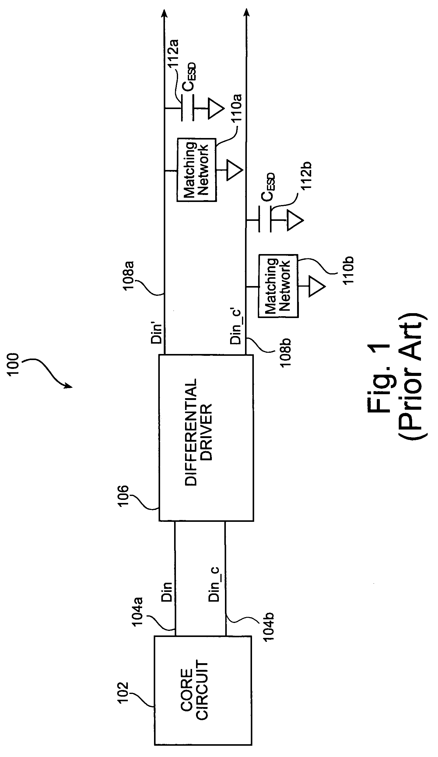
Thus, even though a differential signal output pair has one output signal going high and one output signal going low, a mismatch happens when the signal going low is not lined up (e.g., is offset, slower, faster, etc), with the signal going high of the same differential signal output pair.

Method used


Image

  • Methods and systems for rise-time improvements in differential signal outputs
  • Methods and systems for rise-time improvements in differential signal outputs
  • Methods and systems for rise-time improvements in differential signal outputs

Examples


Embodiment Construction

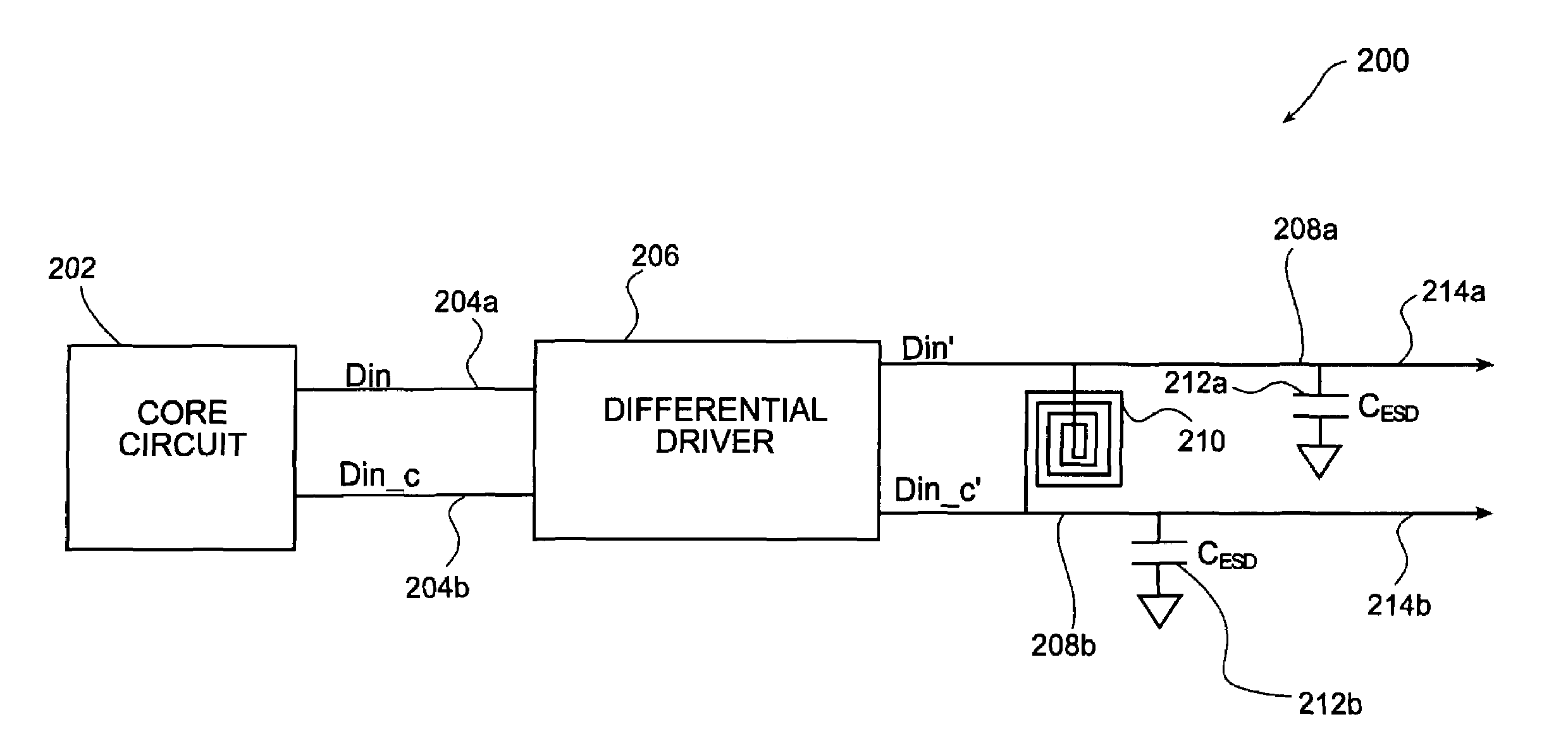
[0034]The present invention, as illustrated by the following embodiments, provides the methods and structures that enable improvements in rise-time performance for single ended outputs, and improvements in rise and fall times for differential output signals. In particular, differential output signals that need to be driven off-chip will benefit from the improvements in rise and fall time performance. As should be appreciated, the present invention can be implemented in various ways, including a method, system, or device. In some instances, well known process operations have not been described in detail in order to avoid obscuring the present invention.

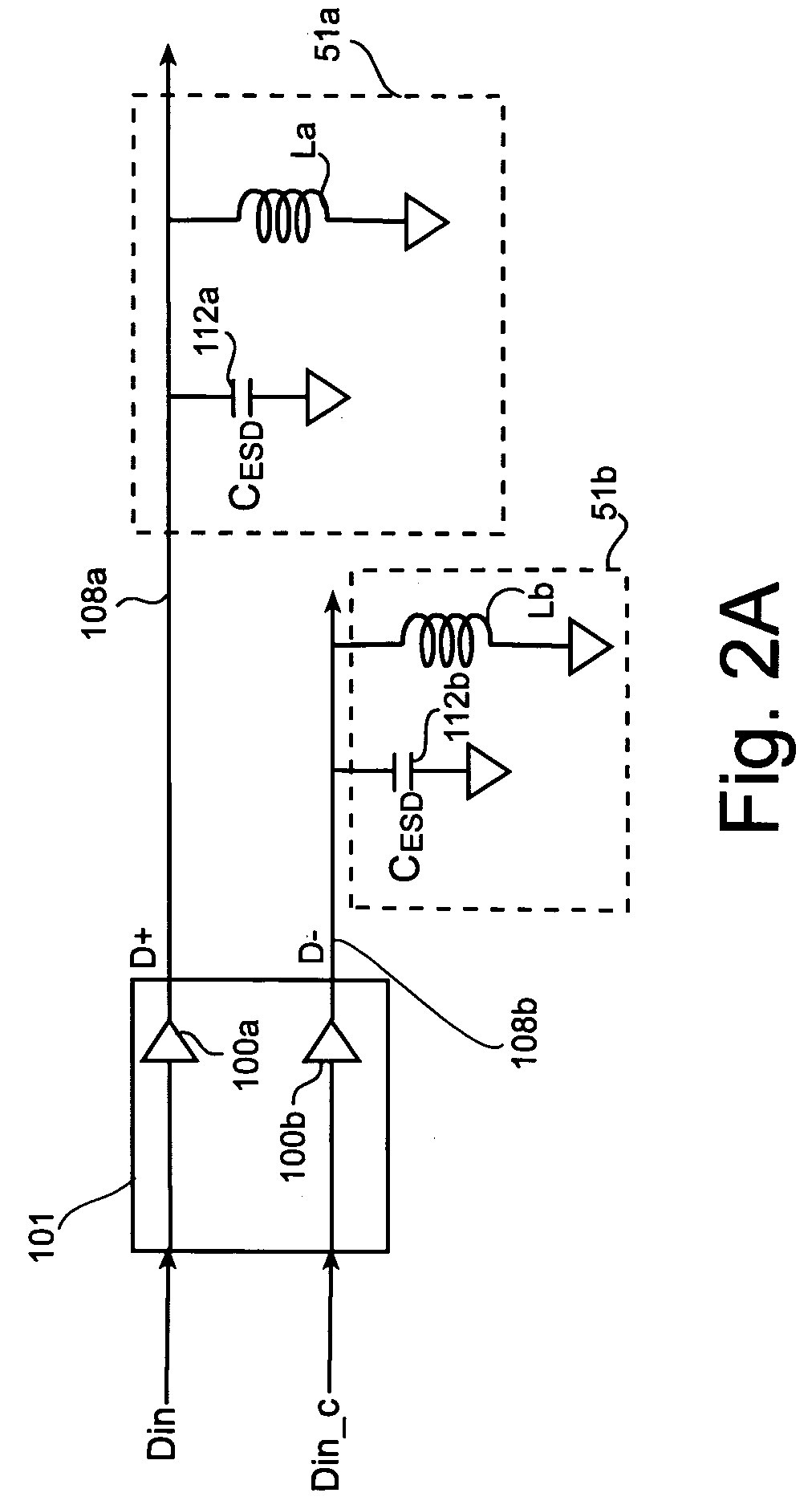
[0035]With reference to FIG. 2A, a differential driver 101 is typically comprised of two single-ended drivers 100a and 100b, each having separate outputs D+ and D− for driving respective output leads 108a and 108b. Each driver 100a and 100b drives the complementary signal of the other. That is, while driver 100a outputs a true signal o...


PUM


Abstract

A method for maintaining signal integrity of a differential output signal generated from a differential driver is disclosed. The method includes receiving the differential output signal from the differential driver. Once received, the method includes tuning the differential output signal by exposing the differential output signal to an inductance. The inductance is configured to reduce signal mismatch between complementary signals of the differential output signal. The signal mismatch is a result of having each of the complementary signals exposed to different capacitive loading. A device and system is also provided, which include integrating an inductor between the output leads of a differential driver. The inductor is sized for the particular frequency of operation, and the inductor provides an inductance that assists in eliminating mismatch between the complementary signals of the differential output. A reduction and / or elimination of the mismatch will assist in improving the rise-time of the differential signals.

Description

BACKGROUND OF THE INVENTION[0001]1. Field of the Invention[0002]This invention relates generally to methods and structures for improving signal transmission in electronic circuits, and more particularly to methods and structures that enable improvements in rise-time performance for differential output signals.[0003]2. Description of the Related Art[0004]In the design and fabrication of electronic circuits, it is well known that capacitive loading, particularly impedance from parasitic capacitance from electrostatic discharge (ESD) protection circuitry, degrades the signal that is being transmitted on conductive traces or leads. As signals are transmitted on conductive leads separated by dielectric materials in a circuit (for example, a circuit fabricated on a multi-layered semiconductor chip), the signals are impeded by parasitic capacitance from the conductive leads. Also, electronic circuits may be subjected to ESD events by simple human handling. As is well known, ESD protection ...

Claims


Application Information

Patent Timeline
Patent Type & Authority Patents(United States)
IPC IPC(8): H03K17/16H03H7/38H01P5/12
CPCH01L23/60H01L23/645H01L24/49H03K19/00323H03K19/013H04L25/0278H01L24/48H01L27/0248H01L2223/6611H01L2224/48091H01L2224/48463H01L2224/4911H01L2924/01005H01L2924/01014H01L2924/01057H01L2924/01082H01L2924/14H01L2924/19042H01L2924/19107H01L2924/30105H01L2924/30107H01L2924/3011H04L25/0272H04L25/028H01L2924/00014H01L2924/01006H01L2924/01033H01L2924/30111H01L2924/00H01L2224/45099H01L2224/05599
Inventor HARGROVE, MICHAELMELTZER, DAVID
Owner SEIKO EPSON CORP
Learn More