All optical regeneration

a technology of all optical regeneration and optical fiber, applied in the field of optical communication systems, can solve the problems of limiting the transmission distance, affecting so as to minimize the error rate and improve the signal extinction ratio

Inactive Publication Date: 2007-05-29
UNIV OF CENT FLORIDA RES FOUND INC +1
View PDF12 Cites 14 Cited by
  • Summary
  • Abstract
  • Description
  • Claims
  • Application Information

AI Technical Summary

Benefits of technology

[0021]The applications of the present invention include all-optical regeneration in long-haul fiber communication systems or optical networks, especially when the signal travel

Problems solved by technology

These systems suffer from many propagation impairments, such as amplified spontaneous-emission (ASE), four-wave mixing (FWM), cross phase modulation (XPM), and stimulated Raman scattering (SRS).
All these effects limit the transmission distance and optical regeneration is necessary to restore optical data signals.
In an all-optical network, the need is even more acute as the optical signal may not only travel over variable distance but also go through unpredictable numbers of switching nodes.
They are expensive since both O-E and E-O conversion are required, and will be finally bandwidth-limited.
Regeneration schemes based on gain dynamics of SOAs are limited in speed by the carrier recovery time and in ER by weak gain saturation.
The speed of operation of this regenerator is limited only by the rise time, not by the carrier recovery time.
The disadvantages of this type of regenerator are as follows.
It is not very practical because of the interferometric stability with long (˜km) length of the fiber loop, and as in the case of SOA based XPM regenerators, it requires preprocessing.
The disadvantages of cross-absorption regenerators are: 1) it has a very low sensitivity (high input power

Method used


Image

  • All optical regeneration
  • All optical regeneration
  • All optical regeneration

Examples


Embodiment Construction

[0041]Before explaining the disclosed embodiments of the present invention in detail it is to be understood that the invention is not limited in its application to the details of the particular arrangements shown since the invention is capable of other embodiments. In addition, the terminology used herein is for the purpose of description and not of limitation.

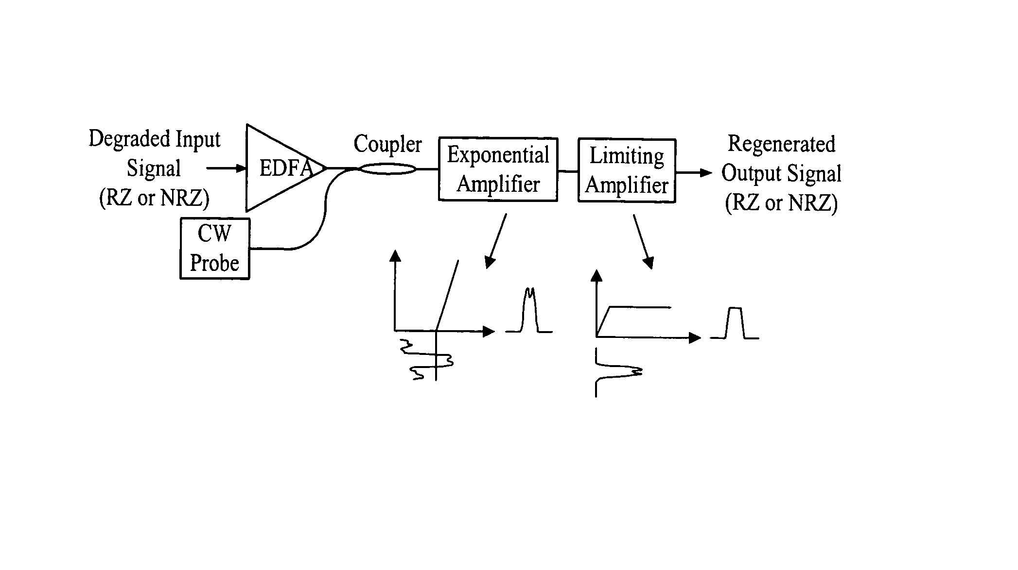
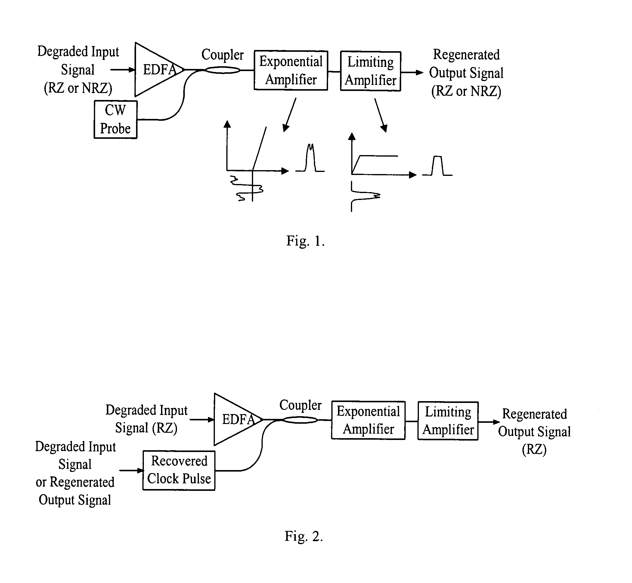
[0042]With respect to the terminology, a short review is presented hereafter for a better understanding of the preferred embodiments. When used in the context of 3R, the reshaping comprises two sub-functions: enhancement of the extinction ratio and noise reduction for bit 0's as well as bit 1's, which are realized by exponential amplification followed by limiting amplification. This invention lists 3 different combinations for the exponential amplification and the limiting amplification as follows: (a) a piece of fiber (dispersion shifted fiber or photonic crystal fiber) with parametric amplification as an exponential amplifie...


PUM


Abstract

All optical regeneration methods and systems can be realized through an exponential amplifier and a limiting amplifier, which could be two independent devices (one piece of fiber with parametric amplification and a semiconductor optical amplifier operating at saturation state) or one single device (one piece of fiber). The signal quality and the extinction ratio after regeneration are significantly improved compared with the degraded incoming data using a parametric amplifier with the data signal to be regenerated as the pump. The regenerated data has an extinction ratio as high as 14 dB, an extinction ratio enhancement of approximately 5 dB and an approximately 5 dB negative power penalty. This regeneration schemes are format transparent (RZ and NRZ), and provide noise reduction both for bit 1's and bit 0's of the data sequence. The regeneration method and apparatus that just utilizes fibers has the additional capability of ultrafast response speed (several femtoseconds due to the Kerr effect).

Description

[0001]This invention claims the benefit of priority to U.S. Provisional patent application Ser. No. 60 / 410,110 filed Sep. 12, 2002.FIELD OF THE INVENTION[0002]This invention relates to optical communication systems, and more particularly to all optical systems and methods of data regeneration after signal degradation occurs due to long distance transmission.BACKGROUND AND PRIOR ART[0003]To meet the growing capacity demand of fiber optic communication system, more channels and higher line-rates have to be considered in dense wavelength-division multiplexing (DWDM) systems. These systems suffer from many propagation impairments, such as amplified spontaneous-emission (ASE), four-wave mixing (FWM), cross phase modulation (XPM), and stimulated Raman scattering (SRS).[0004]All these effects limit the transmission distance and optical regeneration is necessary to restore optical data signals. In an all-optical network, the need is even more acute as the optical signal may not only travel ...

Claims


Application Information

Patent Timeline
IPC IPC(8): G02B6/26
CPCH04B10/299G02B6/02028
Inventor LI, YUHUALI, GUIFANG
Owner UNIV OF CENT FLORIDA RES FOUND INC
Why Eureka
Try Eureka