Method and apparatus to diagnose mechanical problems in machinery

a technology for mechanical problems and machinery, applied in the field of machine tools, can solve problems such as catastrophic failure of machines, inability to inspect each small component subject to failure, and inability to replace easily

Active Publication Date: 2007-05-29
ABB INC
View PDF15 Cites 13 Cited by
  • Summary
  • Abstract
  • Description
  • Claims
  • Application Information

AI Technical Summary

Problems solved by technology

High-valued complex machinery often constitutes a major investment to its owner and is not easily replaced.
Owners of such machinery desire to detect and correct small problems with individual components of such machinery before the small problem leads to catastrophic failure of the machine.
However, it is often impractical to inspect each small component subject to failure on a frequent basis.
The component may be buried deep in the machinery and require many person-hours to remove, inspect and re-install or replace.
In addition to the costs of the person-hours, there is the cost of having the high-valued equipment non-operational for the duration of the inspection procedure.
Such costs are only warranted when the part is sufficiently defective that failure to replace may lead to failure of the high-valued complex machine of which it is part.
This approach is impractical for many reasons and is not taken in practice.
In many machines, there are so many moving components, some very small, that special purpose sensors attached to each one may interfere with required motions, violate required spatial tolerances, increase the cost of the machinery, and otherwise render the machinery unsuitable for its purpose.
Another problem with this approach is that some failure modes are not determined until after the machine is built and operated, and it is impossible to guarantee a sensor that will detect such failure modes before they are discovered.
However, such systems have not been shown to detect small changes in minor components of the machinery.
Such small changes are often dwarfed by the vibrations caused by larger, more energetic components, such as drive shafts.
However, such systems have not been shown to detect small changes in minor components of complex machinery.
Some small components may vary their frequency signature with time during normal operations, so that it is difficult, using fixed frequency bands, to distinguish normal variations from variations associated with an approaching failure of a minor component.

Method used


Image

  • Method and apparatus to diagnose mechanical problems in machinery
  • Method and apparatus to diagnose mechanical problems in machinery
  • Method and apparatus to diagnose mechanical problems in machinery

Examples


Embodiment Construction

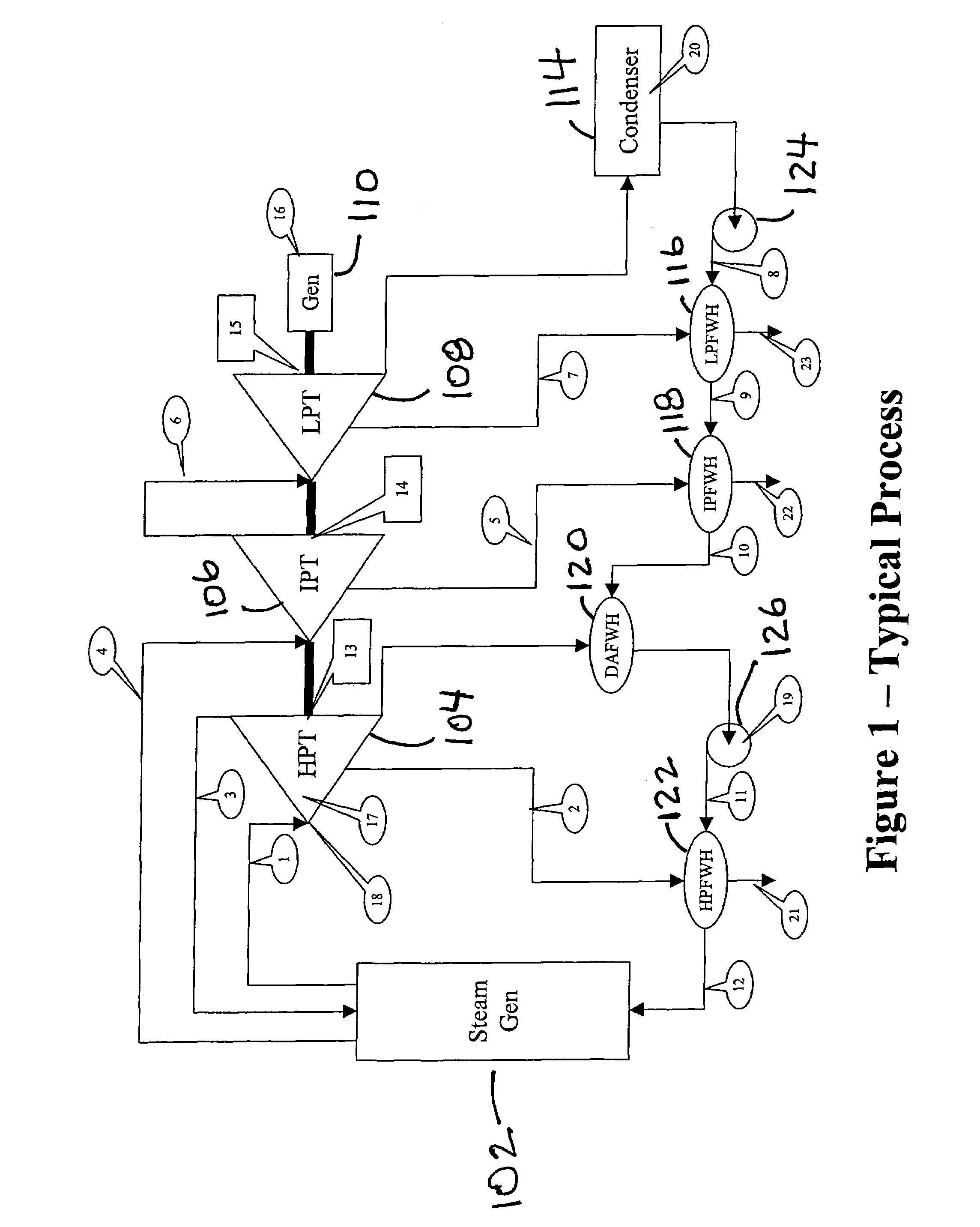
[0041]Referring now to FIG. 1, there is shown a diagram of a process 100 which is the water / steam side of a boiler / turbine power cycle. As is well known to those of ordinary skill in the art, the water / steam side process 100 includes a steam generator 102, a high pressure turbine 104, an intermediate pressure turbine 106, a low pressure turbine 108, a generator 110, a condenser 114, a low pressure feedwater heater 116, an intermediate pressure feedwater heater 118, a de-aerator feedwater heater 120, a high pressure feedwater heater 122, a condensate pump 124 and a boiler feed pump 126. While only one low pressure feedwater heater 116, one intermediate pressure feedwater heater 118 and one high pressure feedwater heater 122 are shown in FIG. 1, it should be appreciated that there are usually multiple heaters 116, 118 and 122 and that one heater is shown in FIG. 1 solely for convenience of illustration. It should also be appreciated that in some plants, heater 118 is located between h...


PUM


Abstract

A method and apparatus for detecting mechanical problems in machinery used in a process. A model of the process is developed using a modeling technique such as advanced pattern recognition and the model is used to generate predicted values for a predetermined number of the operating parameters of the process and vibration parameters of the machinery. Statistical process control methods are used to determine if the difference between the predicted and actual measured values for one or more of the parameters exceeds a configured statistical limit. A rule set is used to indicate an actual or probable fault in the machinery.

Description

CROSS REFERENCE TO RELATED APPLICATION[0001]This application claims the priority of U.S. provisional patent application Ser. No. 60 / 536,356 filed on Jan. 14, 2004, entitled “A Method To Diagnose The Onset Of Mechanical Problems In Rotating Equipment” the contents of which are relied upon and incorporated herein by reference in their entirety, and the benefit of priority under 35 U.S.C. 119(e) is hereby claimed.FIELD OF THE INVENTION[0002]This invention relates to machinery and more particularly to the diagnosis of problems in such equipment.DESCRIPTION OF THE PRIOR ART[0003]High-valued complex machinery often constitutes a major investment to its owner and is not easily replaced. Examples include consumer items such as automobiles and farm equipment, heavy equipment such as trains, cranes, drills and earthmovers, as well as special purpose factory installations such as power generators, assembly line equipment, and power train equipment, such as transmissions, for delivering power t...

Claims


Application Information

Patent Timeline
Patent Type & Authority Patents(United States)
IPC IPC(8): G06F11/30G06F17/18G01H17/00G01M7/00
CPCG01H17/00G05B19/4065G05B2219/32201G05B2219/37435Y02P90/02
Inventor FRERICHS, DONALD KARLTOTH, FRANK MARVINJOHNSON, STEVEN JAMES
Owner ABB INC
Why Eureka
Try Eureka