
Appliance which utilizes a magnetic clutch to transmit power from a drive means to a movable member and a magnetic clutch

Inactive Publication Date: 2007-06-12
POLAR LIGHT
View PDF17 Cites 64 Cited by
  • Summary
  • Abstract
  • Description
  • Claims
  • Application Information

AI Technical Summary

Benefits of technology

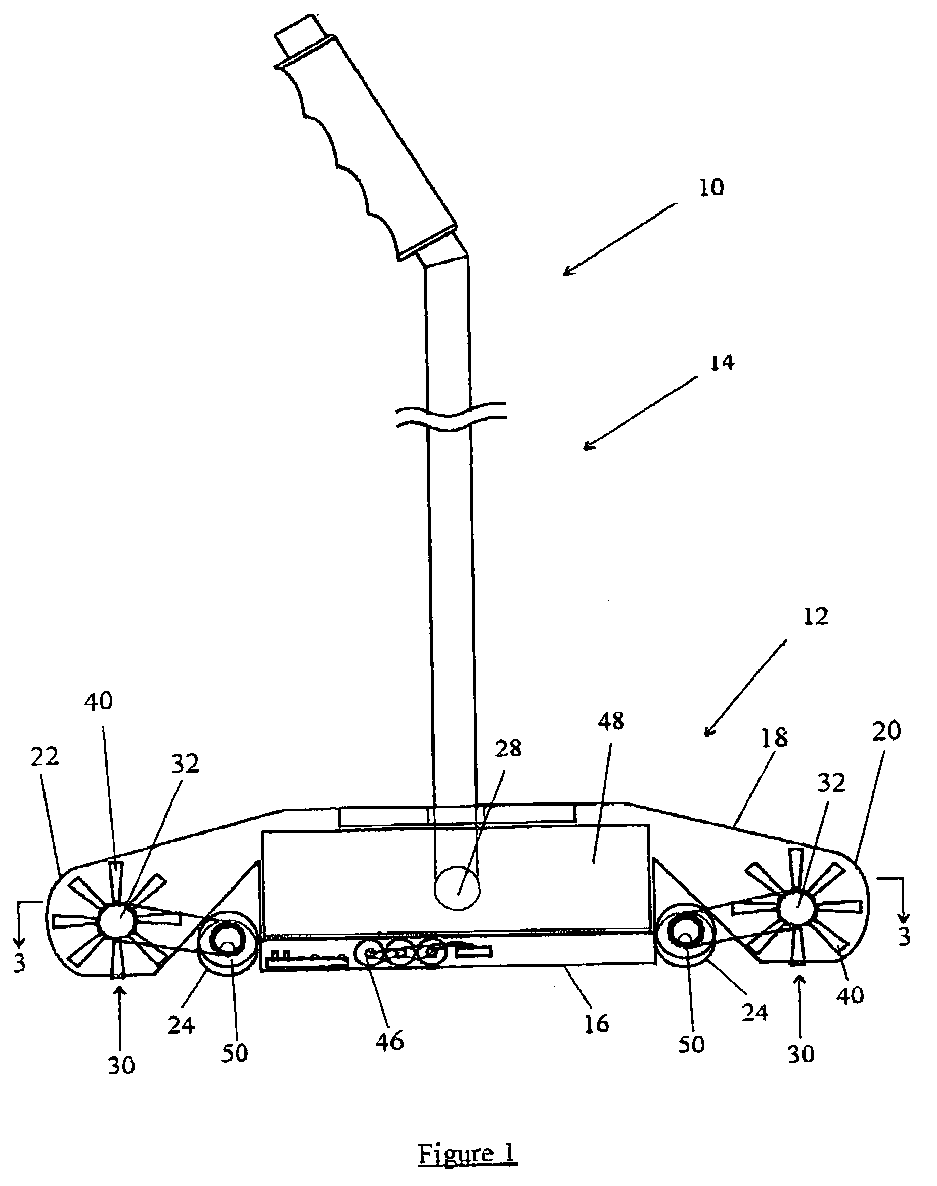
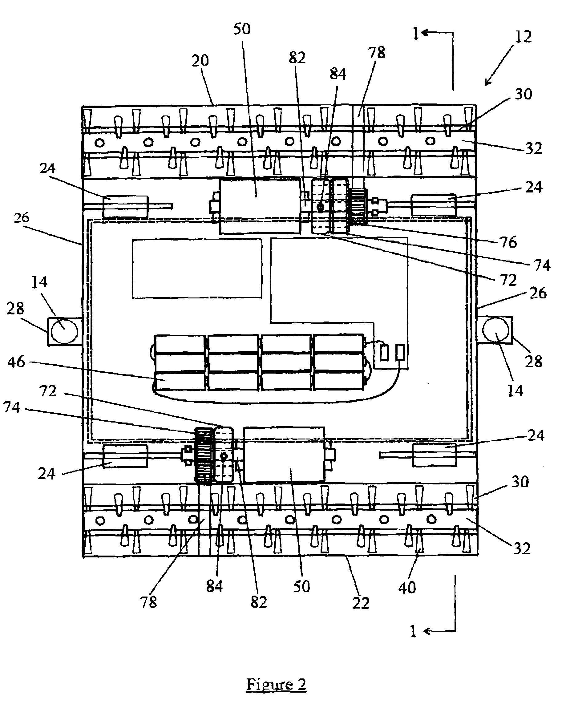
[0005]In accordance with one aspect of the instant invention, a magnetic clutch is utilized in the power transmission coupling between a brush motor and a brush. The magnetic clutch comprises two elements (e.g. opposed plates), which are provided with magnets. Attractive forces between the magnets on the opposed plates will magnetically couple the plates together. Accordingly, the rotation of one plate will cause the other plate to rotate. However, as the plates are not physically connected, if a predetermined amount of torque is applied to one of the plates (e.g. the brush of a vacuum cleaner becomes jammed), the plates will become magnetically decoupled. Accordingly, continued rotation of one of the plates will not cause the opposed plate to rotate thus preventing damage to the brush, any object entangled in the brush as well as the brush motor.
[0006]In accordance with another aspect of the instant invention, a magnetic clutch is used as part or all of the power transmission system between a drive means of an appliance and a moving member that is driven by the drive means. For example, the appliance could be a lawnmower wherein the drive means is the motor of the lawn mower and the moving member, which is driven by the motor, is the cutting blade of the lawn mower. Pursuant to such an embodiment, if the lawn mower blade strikes a solid object (e.g. a rock), the blade will cease rotating due to the disks of the magnetic clutch becoming magnetically decoupled. Similarly, the appliance could be an edge trimmer, a hedge trimmer or other garden implement. In addition, the appliance could be a power tool such as a drill, a skill saw, a jigsaw, a sander or the like. For example, in the case of a drill, the drive means could be the motor of the power tool. The moving member, which is driven by the drive means, could be the chuck in which a drill bit is mounted. According to such an embodiment, if more than a predetermined amount of torque is applied to the drill bit when a hole is being drilled in an object, then the chuck could become magnetically decoupled from the drive motor of the drill thereby preventing damage to the drill bit or overheating of the motor of the drill.
[0007]One advantage of the use of a magnetic clutch in an appliance, such as a vacuum cleaner, garden tool or power tool, is that the movement or rotation of a rotary brush, cutting blade or the reciprocating movement of the blade of a jig saw may be stopped if the moving member becomes jammed or if an excessive restraining force is applied to the moving member without the need of an electric circuit to monitor the current drawn by an electric motor.
[0008]A further advantage is that a magnetic clutch may be employed if the drive means is not an electric motor. For example, the drive means could be an air turbine in the case of a vacuum cleaner or a pneumatic air feed in the case of a power tool. The use of a magnetic clutch does not require monitoring the condition of an electric motor and accordingly may be used regardless of the power source which is utilized to drive the moving member.
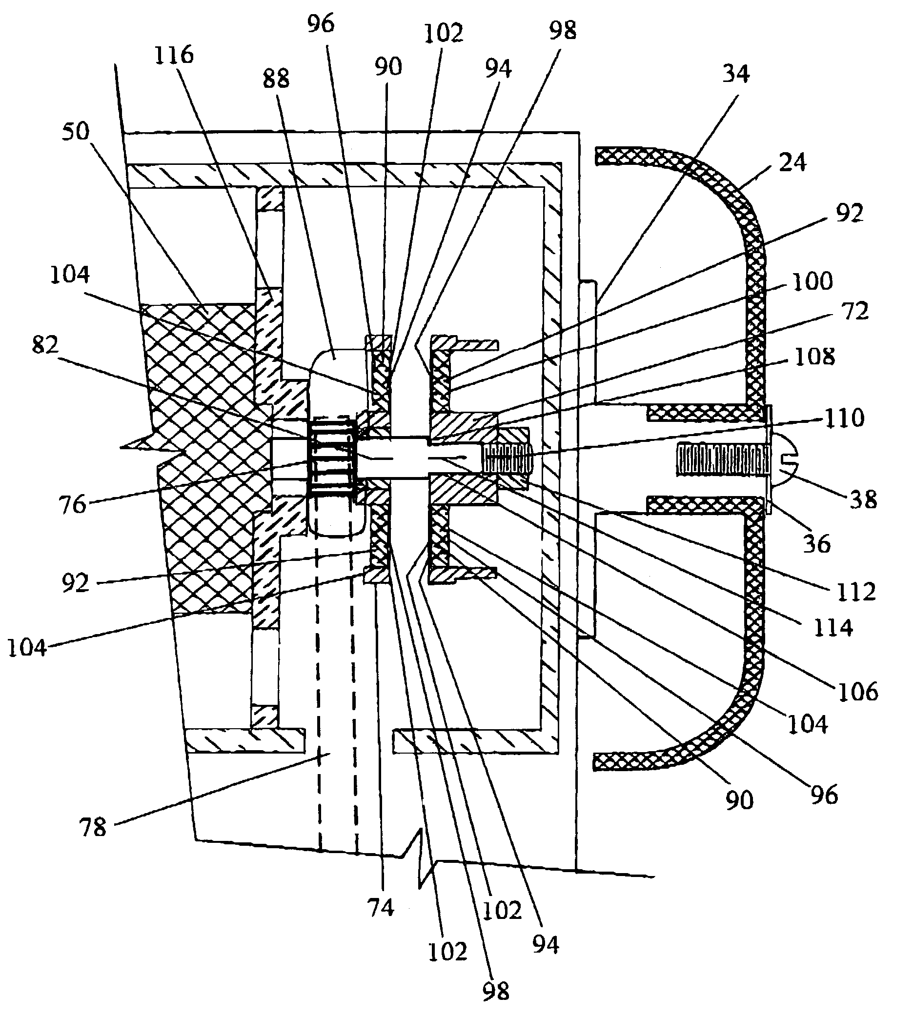
[0010]In accordance with another embodiment of the instant invention, an improved magnetic clutch is disclosed. Pursuant to such an embodiment, the clutch comprises opposed elements each of which contains at least two magnets, the outer poles of which are of opposed or reverse polarity so that, in one orientation, the opposed elements will be magnetically attracted to each other (i.e. magnetically coupled) and, in a second orientation, the opposed elements will be magnetically repelled from each other (i.e. magnetically decoupled). One of the plates is non-rotatably mounted to a shaft (e.g. the shaft of a drive motor). The other of the plates is freely rotatably mounted on a shaft. Accordingly, the opposed plate will only rotate if it is magnetically coupled to the first plate. At lease one of the plates is mounted for lateral motion away from the other plate (e.g. it may be slidably mounted on a shaft). Accordingly, if the plates become magnetically decoupled, the repulsive forces between opposed magnets will cause the plate that is slidably mounted on the shaft to move away from the other opposed plate. If the plates are maintained in closed proximate relationship when they are magnetically decoupled, the induced eddy currents caused by the relative rotation of one plate with respect to the other will result in heating of the magnets provided in the plates. Excessive heating can damage the magnets. An advantage of the embodiment according to this aspect of the invention is that the separation of the magnets, due to the separation of the opposed plates due to the repulsive forces between the magnets on the opposed plates when the plates become magnetically decoupled, reduces the induced heating of the magnets due to the continued rotation of one of the plates with respect to the other when the plates become magnetically decoupled.

Problems solved by technology

However, as the plates are not physically connected, if a predetermined amount of torque is applied to one of the plates (e.g. the brush of a vacuum cleaner becomes jammed), the plates will become magnetically decoupled.

Method used


Image

  • Appliance which utilizes a magnetic clutch to transmit power from a drive means to a movable member and a magnetic clutch
  • Appliance which utilizes a magnetic clutch to transmit power from a drive means to a movable member and a magnetic clutch
  • Appliance which utilizes a magnetic clutch to transmit power from a drive means to a movable member and a magnetic clutch

Examples


Embodiment Construction

[0099]According to a first aspect of this invention, a magnetic clutch is utilized in a surface cleaning apparatus, such as a sweeper, a vacuum cleaner or a carpet cleaner to drivingly connect a brush motor with a rotating or oscillating brush. According to this aspect of the invention, a motive force transmission means is used to drivingly connect the brush motor to the brush. The motive force transmission means may include or consist of a magnetic clutch. The magnetic clutch may be of any particular design that uses the attractive forces between oppositely positioned magnets to transmit the motive force from a brush motor to the brush.

[0100]In accordance with a second aspect of the instant invention, a magnetic clutch is utilized in an appliance and, preferably, an appliance for use in a domestic environment, to connect a drive motor with a moving member. The appliance may be a power tool, such as a power drill, jig saw, a circular saw, a sander, or any other power tool wherein th...


PUM


Abstract

An appliance comprises a moving member, a drive motor, and a linkage drivingly connecting the drive motor to the moving member, the linkage including first and second magnetic coupling members The magnetic clutch may have first and second magnetic coupling members. Each magnetic coupling member has a first surface, which includes at least first and second magnets. Each of the first and second magnets have an outer pole and the outer poles of each of the first magnets and the outer poles of each of the second magnets are of reverse polarity, wherein at least one of the first and second magnetic coupling members is moveably mounted with respect to the other of the first and second magnetic coupling members in a direction perpendicular to the first faces.

Description

FIELD OF THE INVENTION[0001]This invention relates to the transmission of mechanical power from a source of motive force, such as an electric motor, to a movably mounted member. In one aspect, this invention relates to household appliances such as vacuum cleaners, power tools and garden tools which utilize a magnetic clutch for transmitting force from a motor to a rotary brush, cutting member or the like. In another aspect, this invention relates to an improved design for a magnetic clutch.BACKGROUND OF THE INVENTION[0002]It is known in the surface cleaning art to utilize a rotating or oscillating brush to assist in removing dirt from a surface to be cleaned and transporting the dirt into a surface cleaning head of a vacuum cleaner, sweeper or the like. A rotary brush may be powered by an electric motor or an air turbine which may be drivingly connected to the brush by means of a fan belt or by directly mounting the brush on the shaft of the motor or air turbine so as to directly dr...

Claims


Application Information

Patent Timeline
IPC IPC(8): A47L9/04A01B33/08A01D69/08A01G1/12A46B13/00A47L5/30A47L11/32F16D7/00F16D7/02F16D7/04F16D27/01
CPCA01B33/082A01D69/08A01G1/125A47L5/30A47L9/0411A47L9/0444A47L9/0488A47L11/32A47L11/4041A47L11/4069F16D7/00F16D7/025F16D7/046F16D27/01A01D2101/00A46B13/001A46B2200/3066A01G20/47
Inventor CONRAD, WAYNE ERNEST
Owner POLAR LIGHT
Learn More